175A - HP Archive
175A - HP Archive
175A - HP Archive

Create successful ePaper yourself
Turn your PDF publications into a flip-book with our unique Google optimized e-Paper software.
Model <strong>175A</strong> Section V<br />
Paragraphs 5-51 to 5-56<br />
k. Set:<br />
TRIGGER SLOPE (+)<br />
m. Ground green/orange wire which is connected<br />
to TRIGGER SLOPE switch.<br />
n. Adjust Trigger Symmetry R116 for a symmet-<br />
rical square wave display.<br />
p. Unground green/orange wire. Disconnect probe<br />
from CR102 and vertical INPUT. Disconnect Cali-<br />
bration Generator.<br />
5-51. SWEEP LENGTH.<br />
a. Connect Square- Wave Generator 75-ohm output<br />
to vertical INPUT, and set frequency to 1 mc.<br />
b. Set:<br />
HORIZONTAL DISPLAY. ........ X1<br />
TRIGGER SOURCE. ........... INT<br />
TRIGGER LEVEL ............. 0<br />
SWEEP MODE ........... PRESET<br />
SWEEP TIME. ......... lMSEC/CM<br />
c. Set Square Wave Generator output and vertical<br />
SENSITIVITY for approximately 3 cm of deflection.<br />
d. Adjust Sweep Length R161 for 11 cm of sweep.<br />
e. Disconnect Square-Wave Generator.<br />
5-52. SWEEP TIME.<br />
a. Connect Time-Mark Generator to vertical<br />
INPUT.<br />
b. Set:<br />
HORIZONTAL DISPLAY .......... X1<br />
SWEEP MODE ........... PRESET<br />
TRIGGER SOURCE ........... INT<br />
c. Set vertical SENSITIVITY and TRIGGER LEVEL<br />
for a suitable display, and set SWEEP TIME and<br />
marker interval as shown in table 5-4. Make the<br />
corresponding adjustment for the indicated markers<br />
per centimeter if necessary.<br />
d. Disconnect Time-Mark Generator.<br />
SWEEP TIME<br />
.1 ~SEC/CM<br />
.2 ~SEC/CM<br />
.5 LLSEC/CM<br />
1 IJ.SEC/CM<br />
io ~SEC/CM<br />
.I MSEC/CM<br />
1 MSEC/CM<br />
io MSEC/CM<br />
.I SEC/CM<br />
01526-2<br />
Table 5-4. Sweep Time<br />
Markers<br />
Adjust<br />
10 mc C125<br />
5 mc C1016<br />
1 psec C1014<br />
1 psec c1012<br />
10 psec ClOlO<br />
100 psec R1005<br />
1 msec R1004<br />
10 msec R1003<br />
100 msec R1002<br />
Set for<br />
1 cycle/cm<br />
1 cycle/cm<br />
1 marker/2 cm<br />
1 marker/cm<br />
1 marker/cm<br />
1 marker/cm<br />
1 marker/cm<br />
1 marker/cm<br />
1 marker/cm<br />
5-53. =TICAL AM PJn-<br />
5-54. Refer to figure 5-2 for location of adjustments.<br />
5-55. GAIN.<br />
a. Install Model 10404A Vertical Test Adapter into<br />
vertical plug-in connector 51 in place of vertical<br />
plug-in unit.<br />
b. Connect 1.0 volt peak-to-peak from Calibration<br />
Generator to Test Adapter and adjust position control<br />
on adapter for on-scale trace.<br />
c. Adjust Gain R45 for 5 cm deflection.<br />
d. Remove Test Adapter and install vertical plugin<br />
unit.<br />
5-56. SCAN RESPONSE.<br />
a. Connect Square-Wave Generator 75-ohm output<br />
to vertical INPUT and set frequency to 50 kc.<br />
b. Set Square-Wave Generator 75-ohm output and<br />
vertical SENSITIVITY for 6 cm of deflection.<br />
c. Trigger Test Oscilloscope with 600-ohm output<br />
of Square- Wave Generator.<br />
d. Remove horizontal plug-inunit fromModel<strong>175A</strong><br />
and install Test Plug described in paragraph 5-28.<br />
e. Observe signal on pin 15 of horizontal plug-in<br />
connector 5105. Use probe on Test Oscilloscope to<br />
minimize loading.<br />
f. Adjust Scan Response C36 for best square wave<br />
as viewed on Test Oscilloscope.<br />
g. Observe signal on pin 13 of horizontal plug-in<br />
connector 5105.<br />
h. Adjust Scan Response C37 for best square wave<br />
as viewed on Test Oscilloscope.<br />
i. Set frequency of Square- Wave Generator to 1 mc.<br />
j. Observe signal on pin 10 of Test Plug.<br />
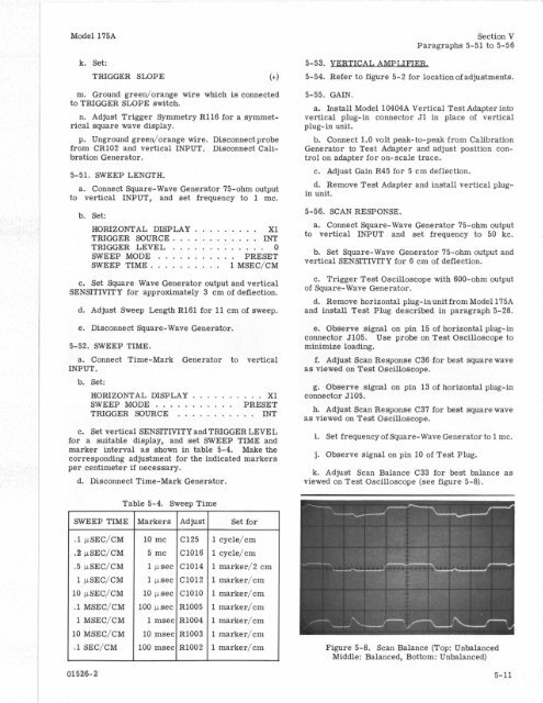
k. Adjust Scan Balance C33 for best balance as<br />
viewed on Test Oscilloscope (see figure 5-8).<br />
Figure 5-8. Scan Balance (Top: Unbalanced<br />
Middle: Balanced, Bottom: Unbalanced)<br />
I<br />
5-11