Download - Brunswick
Download - Brunswick
Download - Brunswick

Create successful ePaper yourself
Turn your PDF publications into a flip-book with our unique Google optimized e-Paper software.
Logic PCB<br />
(2)<br />
EVEN<br />
CAMERA<br />
(3)<br />
ODD<br />
CAMERA<br />
(1)<br />
CONFIGURATION<br />
SWITCH<br />
(NOT USED)<br />
(5)<br />
SIGNAL<br />
INTERCONNECT<br />
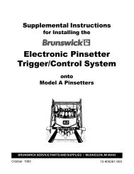
Figure 5. VPS Logic PCB (Top View)<br />
The Logic PCB is responsible for analyzing the video images that it receives<br />
from the two camera mounted in the VPS Chassis. From this information the<br />
board determines the number of standing pins and sends the pin count to the<br />
VPS I/O PCB.<br />
There are no adjustments on the Logic Board. The only setup necessary to the<br />
VPS Processor Board is the triggering of a calibration when the chasiss is first<br />
installed. Refer to Figure 5.<br />
(4)<br />
POWER<br />
INTERCONNECT<br />
(1) CONFIGURATION SWITCH (NOT USED)(2) EVEN CAMERA (3) ODD CAMERA<br />
(4) POWER CONNECT (5) SIGNAL INTERCONNECT<br />
Video Pinsensing System 7