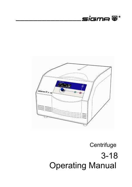
3-18 Operating Manual
3-18 Operating Manual
3-18 Operating Manual

Create successful ePaper yourself
Turn your PDF publications into a flip-book with our unique Google optimized e-Paper software.
———————————————<br />
Centrifuge<br />
3-<strong>18</strong><br />
<strong>Operating</strong> <strong>Manual</strong>
Thank you very much for your confidence in the products of our company.<br />
Our centrifuges are manufactured carefully according to the highest quality standards and we<br />
are sure that your demands will always be fulfilled.<br />
Please read this manual carefully before installation of the centrifuge to ensure a proper and<br />
safe operation.<br />
We are wishing you a successful use of the centrifuge.<br />
SIGMA Laborzentrifugen GmbH<br />
P.O. Box 1713 - 37507 Osterode/Germany<br />
Phone 05522/5007-0 - Fax 05522/500712<br />
Internet: www.sigma-zentrifugen.de<br />
eMail: info@sigma-zentrifugen.de<br />
SIGMA Service-Tel. 05522/5007-25<br />
<strong>Operating</strong> <strong>Manual</strong> SIGMA 3-<strong>18</strong>, page 3 of 95<br />
03/06
Konformitätserklärung<br />
(73/23/EWG; 89/336/EWG; 98/37/EWG)<br />
Statement of Conformity<br />
(73/23/CEE; 89/336/CEE; 98/37/CEE)<br />
Déclaration de conformité<br />
(73/23/CEE; 89/336/CEE; 98/37/CEE)<br />
Die nachfolgend bezeichnete Maschine wurde in Übereinstimmung mit den Richtlinien<br />
73/23/EWG; 89/336/EWG und 98/37/EWG hergestellt und geprüft.<br />
The following machine is manufactured and tested in compliance with directions 73/23/CEE;<br />
89/336/CEE and 98/37/CEE.<br />
La machine désignée ci-dessous est produit et examiné conforme aux directives 73/23/CEE;<br />
89/336/CEE et 98/37/CEE<br />
Bezeichnung der Maschine: Laborzentrifuge<br />
Machine: Laboratory Centrifuge<br />
Désignation de la machine: Centrifugeuse de laboratoire<br />
Maschinentyp : 3 – <strong>18</strong><br />
Type:<br />
Type de la machine:<br />
Bestell Nr. : 10265, 10266, 10267<br />
Part No.:<br />
Réf. usine:<br />
Normen: EN 61010-2-020<br />
Standards: EN 61000-3-2 ; EN 61000-3-3<br />
Normes : EN 61326<br />
Sigma Laborzentrifugen<br />
An der Unteren Söse 50<br />
D-37520 Osterode<br />
27.06.2003 Geschäftsführer<br />
Managing Director<br />
Directeur Gérant<br />
..............................................................…..........<br />
Fabr. Nr. Serial No. Numéro de fabrique<br />
Konformitätserklärung dreisprachig 3-<strong>18</strong> 20030627.DOC<br />
<strong>Operating</strong> <strong>Manual</strong> SIGMA 3-<strong>18</strong>, page 5 of 95<br />
03/06
General Information<br />
1.1 Technical data<br />
1.2 Suitable accessories<br />
1.3 Scope of supply<br />
1.4 Standards and regulations<br />
1.5 Safety instructions<br />
1.6 Symbol table<br />
Description of the Centrifuge<br />
2.1 General outlay<br />
2.2 Construction and constructive safety measures<br />
2.3 Drive<br />
2.4 Operation and display<br />
2.5 Electronic control<br />
2.6 Safety devices<br />
2.6.1 Lid lock, cover closing device<br />
2.6.2 Imbalance monitoring system<br />
2.6.3 Rotor monitoring<br />
2.6.4 Standstill monitoring<br />
2.6.5 System check<br />
2.6.6 Ground wire check<br />
Installation and Start-up<br />
3.1 Unpacking of the centrifuge<br />
3.1.1 Transport safety device<br />
3.2 Installation<br />
3.2.1 Site<br />
3.2.2 Connection/Fuse<br />
3.2.3 Fuses / emergency circuit breaker on site<br />
3.3 Installation of rotors and accessories<br />
3.3.1 Fastening of angle rotors with hermetically sealed lid<br />
3.4 Initial start-up<br />
3.4.1 Switching on of the centrifuge<br />
3.4.2 Opening lid<br />
3.4.3 Installation of a rotor<br />
<strong>Operating</strong> <strong>Manual</strong> SIGMA 3-<strong>18</strong>, page 7 of 95<br />
03/06
<strong>Operating</strong> Elements<br />
4.1 <strong>Operating</strong> panel<br />
4.1.1 Start-key<br />
4.1.2 Stop-key<br />
4.1.3 Lid-key<br />
4.1.4 Knob<br />
4.2 Display<br />
4.2.1 Set<br />
4.2.2 Speed<br />
4.2.3 Relative Centrifugal Force (RCF)<br />
4.2.4 Time<br />
4.2.5 Program<br />
4.2.6 Rotor<br />
4.2.7 Parameters<br />
4.2.7.1 Acceleration<br />
4.2.7.2 Deceleration<br />
4.2.7.3 Radius<br />
4.2.7.4 Density<br />
4.2.7.5 Start delay<br />
4.2.7.6 Automatic lid opening after end of run<br />
4.2.8 Configuration<br />
Operation<br />
5.1 Selection, display and alteration of program parameters<br />
5.1.1 Selection and alteration of the parameters and activation of the start<br />
delay and the automatic lid opening after end of run<br />
5.1.2 Selection and alteration of the rotor part number<br />
5.1.3 Alteration of the parameter values during the centrifuge run<br />
5.1.4 Alteration of the configuration<br />
5.1.4.1 Curves<br />
5.1.4.2 Creation of curves for variable accelerations and decelerations<br />
5.1.4.3 Alteration of existing curves<br />
5.1.5 Alteration of the contrast<br />
5.1.6 Imbalance monitoring<br />
5.1.7 Shortrun and faststop<br />
6 Programming<br />
6.1 Load, save and delete programs<br />
6.1.1 Load a program<br />
6.1.2 Save a program<br />
6.1.3 Delete a program<br />
<strong>Operating</strong> <strong>Manual</strong> SIGMA 3-<strong>18</strong>, page 8 of 95<br />
03/06
Notes for Centrifugation<br />
7.1 Practical notes for centrifugation<br />
7.2 Forbidden centrifuging operations<br />
Care and Maintenance<br />
8.1 Care and cleaning of centrifuge<br />
8.2 Care and cleaning of accessories<br />
8.3 Rotor pins/Motorized lid lock<br />
8.4 Glass breakage<br />
8.5 Sterilization and disinfection of rotor chamber and accessories<br />
8.5.1 Autoclaving<br />
8.6 Checks by operator<br />
Appendix<br />
9.1 Slope of the specified curves, linear curves<br />
9.2 Quadratic curves<br />
9.3 Entry limitations<br />
9.4 Mathematical relations<br />
9.4.1 Relative Centrifugal Force (RCF)<br />
9.4.2 Density<br />
9.5 Error correction<br />
9.5.1 Centrifuge cannot be started<br />
9.5.2 Centrifuge decelerates during operation<br />
9.5.3 Lid cannot be opened/closed<br />
9.5.4 Emergency lid release<br />
9.5.5 Problems with the centrifuge?<br />
9.6 Error codes<br />
9.7 Speed-RCF-diagram<br />
9.8 Declaration of decontamination/Return declaration<br />
9.9 Form program data<br />
9.10 Leaflet<br />
<strong>Operating</strong> <strong>Manual</strong> SIGMA 3-<strong>18</strong>, page 9 of 95<br />
03/06
1.1 Technical Data<br />
Manufactuer: S I G M A<br />
Laborzentrifugen GmbH<br />
37520 Osterode, Germany<br />
Type: 3-<strong>18</strong><br />
Electr. connection:<br />
see nameplate<br />
Protection class:<br />
I<br />
Rated power (kW):<br />
0.44<br />
Max. current (A):<br />
Power data:<br />
2.6 (230 V/50 Hz)<br />
5.1 (120 V/60 Hz)<br />
Max. speed (rpm):<br />
16 000<br />
Max. capacity (l):<br />
1<br />
Max. gravitational field (x g):<br />
23 469<br />
Max. kin. energy (Nm):<br />
Further parameters<br />
9 530<br />
Time range:<br />
9 h, 59 min/continuous operation<br />
Programs:<br />
50 No. 1 - 50<br />
Acceleration curves:<br />
10 linear No. 0 - 9<br />
10 quadratic No. 10 - 19<br />
10 freely programmable<br />
No. 20 - 29<br />
Deceleration curves:<br />
9 linear No. 1 - 9<br />
1 brakeless No. 0<br />
10 quadratic No. 10 - 19<br />
10 freely programmable<br />
No. 20 – 29<br />
Radius:<br />
max./min. see chapter 1.2<br />
Rotor part no.:<br />
Dimensions:<br />
see chapter 1.2<br />
Depth (mm):<br />
600<br />
Width (mm):<br />
460<br />
Height (mm):<br />
355<br />
Weight (kg):<br />
48<br />
EMC (acc. to EN 55011):<br />
Class B<br />
Noise level (dBA):<br />
< 70<br />
Notes of user:<br />
Serial number:<br />
Supply date:<br />
Inventory number:<br />
Location:<br />
Responsibility:<br />
.....................................................<br />
.....................................................<br />
.....................................................<br />
.....................................................<br />
.....................................................<br />
The figures are valid for an ambient temperature of 23 °C +/- 2 °C and nominal voltage +/- 5 %.<br />
(Allowable ambient temperature +4 °C - +40 °C; max. humidity 80 %.)<br />
Subject to technical alterations.<br />
<strong>Operating</strong> <strong>Manual</strong> SIGMA 3-<strong>18</strong>, page 11 of 95<br />
03/06
1.2 Accessories Suitable for SIGMA 3-<strong>18</strong><br />
Part No.<br />
Description<br />
11<strong>18</strong>0 Swing-out rotor for 4 buckets for the<br />
following accessories:<br />
13194 Bucket for rectangular carriers <strong>18</strong>310,<br />
<strong>18</strong>311 (culture tubes 15 resp. 50 ml), max.<br />
radius 16.8 cm, min. radius 6.6 cm<br />
<strong>18</strong>310 Rectangular carrier for 4 culture tubes<br />
50 ml, e.g. 15151<br />
<strong>18</strong>311 Rectangular carrier for 10 culture tubes<br />
15 ml, e.g. 15115<br />
13<strong>18</strong>0 Rectangular bucket, aluminium, sealable<br />
with cap 17112, suitable for the system of<br />
rectangular carriers, suitable for 11<strong>18</strong>0,<br />
max. radius 17.1 cm, min. radius 7.6 cm<br />
17112 Sealing cap, polysulfone, clear, incl. 2 clips<br />
171<strong>18</strong>, suitable for 13<strong>18</strong>0<br />
<strong>18</strong>000 Rectangular carrier, undrilled for special<br />
tubes 85 - 110 mm long, polyallomer<br />
<strong>18</strong>002 Rectangular carrier for 20 reaction vials<br />
1.5 - 2.2 ml, max. ∅ 11 mm, e.g. 15008,<br />
15040, polypropylene<br />
<strong>18</strong>003 Upper part for <strong>18</strong>002 for 20 reaction vials<br />
1.5 - 2.2 ml, e.g. 15008, 15040, can be used<br />
together with <strong>18</strong>002, polypropylene<br />
<strong>18</strong>005 Rectangular carrier for 20 RIA-tubes 5 ml,<br />
max. ∅ 12.2 x 60 - 75 mm, flat and round<br />
bottom tubes, e.g. 15060, polyallomer<br />
<strong>18</strong>007 Rectangular carrier for 20 glass tubes 7 ml,<br />
max. ∅ 12.3 x 80 - 105 mm, flat and round<br />
bottom tubes, e.g. 15007, 15027,<br />
polyallomer<br />
Max. speed<br />
(rpm)<br />
4 200<br />
4 200<br />
4 200<br />
Max.<br />
gravitational<br />
field (x g)<br />
3 372/3 392<br />
3 313<br />
3 372<br />
<strong>Operating</strong> <strong>Manual</strong> SIGMA 3-<strong>18</strong>, page 13 of 95<br />
03/06
Part No.<br />
Description<br />
<strong>18</strong>009 Rectangular carrier for 20 hemolyse tubes,<br />
max. ∅ 12.8 x 70 - 90 mm, polypropylene<br />
<strong>18</strong>010 Rectangular carrier for 12 tubes with screw<br />
cap 10 - 12 ml, max. ∅ 16.8/17.5 x 60 -<br />
85 mm, e.g. 15000, 15010, 15039,<br />
polyallomer<br />
<strong>18</strong>012 Rectangular carrier for 12 Vacutainer-tubes<br />
∅ 13.5/<strong>18</strong> x 65 - 90 mm, polypropylene<br />
<strong>18</strong>015 Rectangular carrier for 12 tubes 10 - 15 ml,<br />
max. ∅ 17 x 90 - 105 mm, e.g. 15015, 15020,<br />
15022, 15023, 15024, polyallomer<br />
<strong>18</strong>016 Rectangular carrier for 4 culture tubes<br />
15 ml 15115, polypropylene<br />
<strong>18</strong>017 Rectangular carrier for 10 tubes 15 ml, and<br />
tubes with stopper, max. Ø 17.2/<strong>18</strong> x 80 -<br />
111 mm, e.g. Monovettes 9 ml and 10 ml,<br />
polypropylene<br />
<strong>18</strong>025 Rectangular carrier for 5 glass tubes 25 ml,<br />
max. ∅ 24 x 85 - 105 mm, e.g. 15025, 15026,<br />
polyallomer<br />
<strong>18</strong>022 Rectangular carrier for 4 sterilin tubes<br />
30 ml, graduated up to 20 ml, with skirt,<br />
incl. cap, max. ∅ 25/31 x 65 - 95 mm,<br />
polypropylene, see www.bibby-sterilin.co.uk,<br />
no. 03008<br />
<strong>18</strong>030 Rectangular carrier for 5 tubes with screw<br />
cap 27 - 30 ml, max. ∅ 25.4/27.5 x 80 -<br />
110 mm, e.g. 15029, 15030, 15032,<br />
polypropylene<br />
<strong>18</strong>050 Rectangular carrier for 2 tubes 50 ml, max.<br />
∅ 35/38 x 85 - 110 mm, e.g. 15049, 15050,<br />
15056, polyallomer<br />
Max. speed<br />
(rpm)<br />
Max.<br />
gravitational<br />
field (x g)<br />
<strong>Operating</strong> <strong>Manual</strong> SIGMA 3-<strong>18</strong>, page 14 of 95<br />
03/06
Part No.<br />
Description<br />
<strong>18</strong>051 Rectangular carrier for 2 tubes with screw<br />
cap 40 - 50 ml, max. ∅ 29/35 x 80 - 110 mm,<br />
e.g. 13055, 15051, 15052, 15054,<br />
polypropylene<br />
<strong>18</strong>052 Rectangular carrier for 2 culture tubes<br />
50 ml 15151, polypropylene<br />
<strong>18</strong>053 Rectangular carrier for 2 culture tubes<br />
50 ml with skirt, max. ∅ 29.5/38 x 85 -<br />
1<strong>18</strong> mm, polypropylene<br />
<strong>18</strong>085 Rectangular carrier for 1 tube with screw<br />
cap 78 - 85 ml, max. ∅ 38/40 x 85 - 112 mm,<br />
e.g. 13085, 15074, 15075, 15076, 15080,<br />
polyallomer<br />
<strong>18</strong>100 Rectangular carrier for 1 tube 100 ml, max.<br />
∅ 45.5/48 x 85 - 110 mm, e.g. 15100, 15102,<br />
15103, 15106, polyallomer<br />
<strong>18</strong>105 Rectangular carrier for 20 RIA-tubes 5 ml,<br />
max. ∅ 12.2 x 60 - 75 mm, flat and round<br />
bottom tubes, e.g. 15060, decantable,<br />
polyallomer<br />
<strong>18</strong>107 Rectangular carrier for 20 glass tubes 7 ml,<br />
max. ∅ 12.3 x 80 - 105 mm, flat and round<br />
bottom tubes, e.g. 15007, 15027,<br />
decantable, polyallomer<br />
<strong>18</strong>115 Rectangular carrier for 12 tubes 10 - 15 ml,<br />
max. ∅ 17 x 90 - 105 mm, e.g. 15015, 15020,<br />
15022, 15023, 15024, decantable,<br />
polyallomer<br />
<strong>18</strong>125 Rectangular carrier for 1 bottle with screw<br />
cap 125 ml, max. ∅ 51 x 90 - 115 mm, e.g.<br />
15125, polypropylene<br />
<strong>18</strong>200 Rectangular carrier for 1 bottle with screw<br />
cap 200 ml, max. ∅ 57 x 90 - 115 mm, e.g.<br />
15202, 15203, polypropylene<br />
Max. speed<br />
(rpm)<br />
Max.<br />
gravitational<br />
field (x g)<br />
<strong>Operating</strong> <strong>Manual</strong> SIGMA 3-<strong>18</strong>, page 15 of 95<br />
03/06
Part No.<br />
Description<br />
11<strong>18</strong>1 Swing-out rotor 48 x 15 ml complete, consisting<br />
of rotor 11<strong>18</strong>0, 4 rectangular<br />
buckets 13<strong>18</strong>0, 4 carriers <strong>18</strong>015 and 48 PStubes<br />
15020, max. radius 17.1 cm, min.<br />
radius 7.6 cm<br />
11<strong>18</strong>2 Swing-out rotor 12 x 50 ml culture tubes<br />
complete, consisting of rotor 11<strong>18</strong>0,<br />
4 round buckets 13190, 4 carriers 17346<br />
and 12 culture-tubes 15151, max. radius<br />
17.2 cm, min. radius 7.5 cm<br />
13190 Round bucket, aluminium, sealable with<br />
cap 17190, suitable for the following round<br />
carriers, suitable for 11<strong>18</strong>0, max. radius<br />
17.2 cm, min. radius 7.5 cm<br />
17190 Sealing cap, polysulfone, clear, suitable for<br />
13190<br />
17350 Round carrier for 24 reaction vials 0.5 -<br />
0.75 ml, ∅ 8/10 x 28/31 mm, e.g. 15005,<br />
polypropylene<br />
17351 Round carrier for 12 Monovettes, max.<br />
∅ 15.5/<strong>18</strong> x 50 - 75 mm, polypropylene<br />
17352 Round carrier for 25 RIA-tubes, max. ∅ 12.5<br />
x 65 - 80 mm, e.g. 15060, polypropylene<br />
17353 Round carrier for 16 reaction vials 1.5 -<br />
2.2 ml, max. ∅ 11 mm, e.g. ml 15008, 15040,<br />
polypropylene<br />
17354 Round carrier for 16 glass tubes 7 ml, max.<br />
∅ 12.5 x 85 - 115 mm, e.g. 15007, 15027,<br />
polypropylene<br />
17355 Round carrier for 12 tubes with screw cap<br />
10 - 12 ml, max. ∅ 16.2/19 x 65 - 90 mm, e.g.<br />
15000, 15010, 15039, polypropylene<br />
17356 Round carrier for 16 Vacutainer/hemolyse<br />
tubes/RIA-tubes 5 - 6 ml, max. ∅ 13.5/17.5 x<br />
70 - 90 mm, e.g. 15060, polypropylene<br />
Max. speed<br />
(rpm)<br />
4 200<br />
4 200<br />
4 200<br />
Max.<br />
gravitational<br />
field (x g)<br />
3 372<br />
3 392<br />
3 392<br />
<strong>Operating</strong> <strong>Manual</strong> SIGMA 3-<strong>18</strong>, page 16 of 95<br />
03/06
Part No.<br />
Description<br />
17358 Round carrier for 12 tubes 10 - 15 ml, max.<br />
∅ 17.2/19.5 x 90 - 115 mm, e.g. 15015,<br />
15020, 15022, 15023, 15024, and<br />
Monovettes 9 ml and 10 ml, polypropylene<br />
17345 Round carrier for 5 culture tubes 15 ml<br />
15115, polypropylene<br />
17362 Round carrier for 5 sterilin tubes 30 ml,<br />
graduated up to 20 ml, with skirt, incl. cap,<br />
max. ∅ 25/31 x 65 - 95 mm, polypropylene,<br />
see www.bibby-sterilin.co.uk, no. 03008<br />
17370 Round carrier for 5 tubes 25 - 30 ml, max. ∅<br />
25.4/29 x 85 - 115 mm, e.g. 15025, 15026,<br />
15029, 15030, 15032, 15033, polypropylene<br />
17375 Round carrier for 3 tubes 50 ml, max.<br />
∅ 35/38 x 90 - 110 mm, e.g. 15049, 15050,<br />
15056, polypropylene<br />
17376 Round carrier for 4 tubes with screw cap<br />
40 - 50 ml, max. ∅ 29/34 x 85 - 110 mm, e.g.<br />
15051, 15052, 15054, polypropylene<br />
17346 Round carrier for 3 culture tubes 50 ml<br />
15151, polypropylene<br />
17385 Round carrier for 1 tube with screw cap<br />
78 - 85 ml, max. ∅ 38/40 x 85 - 115 mm, e.g.<br />
13085, 15074, 15075, 15076, 15080,<br />
polypropylene<br />
17390 Round carrier incl. rubber cushion 16051<br />
for 1 tube 100 ml, max. ∅ 45/50 x 85 -<br />
110 mm, e.g. 15100, 15102, 15103, 15106,<br />
polypropylene<br />
17395 Round carrier for 1 bottle with screw cap<br />
125 ml, max. ∅ 51 x 90 - 115 mm, e.g. 15125,<br />
polypropylene<br />
17400 Round carrier for 1 bottle with screw cap<br />
200 ml, max. ∅ 57 x 90 - 115 mm, e.g. 15202,<br />
15203, polypropylene<br />
Max. speed<br />
(rpm)<br />
Max.<br />
gravitational<br />
field (x g)<br />
<strong>Operating</strong> <strong>Manual</strong> SIGMA 3-<strong>18</strong>, page 17 of 95<br />
03/06
Part No.<br />
Description<br />
17347 Round carrier for 1 bottle with screw cap<br />
250 ml, max. ∅ 61.5 x 90 - 125 mm, e.g.<br />
15247, 15248, 15249, polypropylene<br />
11240 Swing-out rotor for microtiter-plates, incl. 2<br />
buckets 13145 and plate holder 17977,<br />
radius edge 12.7 cm,<br />
radius max. 10.5 cm<br />
radius min. 4.65 cm,<br />
max. plate height 64 mm<br />
11222 Swing-out rotor for microtiter plates, incl. 2<br />
carriers 13222<br />
radius edge 12.3 cm,<br />
radius max. 10.5 cm,<br />
radius min. 6.5 cm<br />
max. plate height 56 mm<br />
11133 Swing-out rotor for 4 round buckets, for the<br />
following accessories:<br />
13104 Round bucket, aluminium, sealable with<br />
caps 17109, 17111, for the following round<br />
carriers and the 200 ml bottles 15202 and<br />
15203, suitable for 11133, max. radius<br />
16.1 cm, min. radius 5.7 cm:<br />
17109 Sealing cap, aluminium, for hermetic<br />
sealing of bucket 13104<br />
17111 Sealing cap, polysulfone, clear, for<br />
hermetic sealing of bucket 13104<br />
13117 Round bucket, aluminium, for the following<br />
round carriers and the 200 ml bottles 15202<br />
and 15203, suitable for 11133, max. radius<br />
16.1 cm, min. radius 5.7 cm<br />
17000 Round carrier, two-piece, undrilled, for<br />
tubes 90 - 110 mm long, polyallomer<br />
17006 Round carrier for 12 tubes 5 ml, max. ∅<br />
12.5 x 55 - 75 mm, e.g. hemolyse tubes or<br />
RIA-tubes 15060, polyallomer<br />
Max. speed<br />
(rpm)<br />
3 850<br />
3 000<br />
5 000<br />
5 000<br />
5 000<br />
Max.<br />
gravitational<br />
field (x g)<br />
2 105<br />
1 740<br />
770<br />
1 238<br />
1 057<br />
654<br />
4 500<br />
4 500<br />
4 500<br />
<strong>Operating</strong> <strong>Manual</strong> SIGMA 3-<strong>18</strong>, page <strong>18</strong> of 95<br />
03/06
Part No.<br />
Description<br />
17007 Round carrier for 12 glass tubes 7 ml, max.<br />
∅ 12.3 x 90 - 105 mm, e.g. 15007, 15027,<br />
polyallomer<br />
17008 Round carrier for 12 reaction vials 1,5 -<br />
2,2 ml, max. ∅ 11 mm, e.g. 15008, 15040,<br />
polypropylene<br />
17027 Round carrier for 7 Vacutainer-tubes, max.<br />
∅ 13.5/17.5 x 65 - 90 mm, polypropylene<br />
17012 Round carrier for 6 tubes with screw cap<br />
10 - 12 ml, max. ∅ 16.5/17.5 x 58 -90 mm,<br />
e.g. 15000, 15010,15039, polyallomer<br />
17013 Round carrier for 9 hemolyse tubes, max. ∅<br />
12,9 x 85 mm, polypropylene<br />
17015 Round carrier for 7 tubes 10 - 15 ml, max. ∅<br />
16.8 x 90 - 105 mm, e.g. 15015, 15020,<br />
15022, 15023, 15024, polyallomer<br />
170<strong>18</strong> Round carrier for 4 tubes with sealing cap<br />
10 - 15 ml, max. ∅ 17/20 x 90 - 110 mm and<br />
Monovettes, polyallomer<br />
17019 Round carrier for 3 culture tubes 15 ml<br />
15115, polypropylene, suitable for 13104<br />
without sealing cap<br />
17025 Round carrier for 2 glass tubes 25 ml, max.<br />
∅ 24.5 x 90 - 105 mm, e.g. 15025, 15026,<br />
polyallomer<br />
17032 Round carrier for 1 sterilin tube 30 ml,<br />
graduated up to 20 ml, with skirt, incl. cap,<br />
max. ∅ 25/31 x 65 - 95 mm, polypropylene,<br />
see www.bibby-sterilin.co.uk, no. 03008<br />
17030 Round carrier for 2 tubes with screw cap<br />
27 - 30 ml, max. ∅ 25.4/27.5 x 85 - 100 mm,<br />
e.g. 15029, 15030, 15032, polypropylene<br />
17049 Round carrier for 1 culture tube 50 ml<br />
15151, polypropylene<br />
Max. speed<br />
(rpm)<br />
Max.<br />
gravitational<br />
field (x g)<br />
<strong>Operating</strong> <strong>Manual</strong> SIGMA 3-<strong>18</strong>, page 19 of 95<br />
03/06
Part No.<br />
Description<br />
17050 Round carrier for 1 tube 50 ml, max. ∅<br />
35/38 x 85 - 115 mm, e.g. 15049, 15050,<br />
15056, polyallomer<br />
17052 Round carrier for 1 tube with screw cap<br />
40 - 50 ml, max. ∅ 29/35 x 85 - 115 mm, e.g.<br />
13055, 15051, 15052, 15054, polyallomer<br />
17085 Round carrier for 1 tube with screw cap<br />
78 - 85 ml, max. ∅ 38/40 x 85 - 112 mm, e.g.<br />
13085, 15074, 15075, 15076, 15080,<br />
polyallomer<br />
17100 Round carrier for 1 tube 100 ml, max.<br />
∅ 45.5 x 85 - 105 mm, e.g 15100, 15103,<br />
15106, polyallomer<br />
17101 Round carrier for 1 tube 100 ml, max.<br />
∅ 45.5 x 85 - 105 mm, e.g. 15100, 15102,<br />
15103, 15106, polypropylene<br />
17125 Adapter for 1 bottle with screw cap 125 ml,<br />
max. ∅ 51 x 90 - 120 mm, e.g. 15125,<br />
polypropylene<br />
11132 Swing-out rotor 28 x 15 ml complete, consisting<br />
of rotor 11133, 4 round buckets<br />
13117, 4 carriers 17015 and 28 PS-tubes<br />
15020, max. radius 14.9 cm, min. radius<br />
5.7 cm<br />
11224 Swing-out rotor for cytology, complete,<br />
incl. 4 buckets and carriers for different<br />
object carriers. The buckets with object<br />
carriers could be locked in 90° position,<br />
max. radius 11.3 cm<br />
11136 Rotor for reaction vials (max. 60/120 pcs.)<br />
incl. cover, for carriers 14000, 14002, 14020<br />
and 14021, max. radius 7 cm, min. radius 3<br />
cm. Attention: The vessels could be<br />
damaged at speeds exceeding 13 000 rpm<br />
14000 Casset for 20 reaction vials 0.25 - 0.4 ml<br />
15014, suitable for 11136, polyallomer<br />
Max. speed<br />
(rpm)<br />
5 000<br />
3 000<br />
13 000<br />
Max.<br />
gravitational<br />
field (x g)<br />
4 165<br />
1 137<br />
13 226<br />
<strong>Operating</strong> <strong>Manual</strong> SIGMA 3-<strong>18</strong>, page 20 of 95<br />
03/06
Part No.<br />
Description<br />
14002 Casset for 10 reaction vials 1.5 - 2.2 ml<br />
15008, 15040, suitable for 11136,<br />
polyallomer<br />
14020 Casset for 10 PCR tubes 0.2 - 0.5 ml,<br />
suitable for 11136, polypropylene<br />
14021 Casset for 32 PCR tubes 0.2 ml or 4 strips<br />
with 8 PCR tubes 0.2 ml each, suitable for<br />
11136, polypropylene<br />
11135 Swing-out rotor 24 x 1.5 - 2.2 ml for reaction<br />
vials e.g. 15008, 15040, incl. hermetic<br />
aluminium lid, max. radius 7.4 cm, min.<br />
radius 3.5 cm<br />
12154 Angle rotor 24 x 1.5 - 2.2 ml for reaction<br />
vials e.g. 15008, 15040, incl. hermetic<br />
aluminium lid, max. radius 8.2 cm, min.<br />
radius 5 cm, angle 45°<br />
12131 Angle rotor 30 x 1.5 - 2.2 ml for reaction<br />
vials e.g. 15008, 15040, incl. hermetic<br />
aluminium lid, max. radius10 cm, min.<br />
radius 6.7 cm, angle 45°<br />
12348 Angle rotor 48 x 1.5 - 2.2 ml for reaction<br />
vials e.g. 15008, 15040, incl. hermetic<br />
aluminium lid, max. radius 8.4 cm, min.<br />
radius 5.1 cm<br />
12115 Angle rotor for 12 strips with 8 PCR tubes<br />
0.2 ml each, incl. hermetic aluminium lid,<br />
max. radius 9.8 cm, min. radius 7.2 cm,<br />
angle 45°<br />
12111 Angle rotor 10 x 10 - 12 ml for sealed tubes<br />
15000, 15010, 15039, incl. hermetic<br />
aluminium lid, max. radius 7.6 cm, min.<br />
radius 2.8 cm, angle 35°<br />
12157 Angle rotor 20 x 10 - 12 ml for sealed tubes<br />
15000, 15010, 15039, incl. hermetic<br />
aluminium lid, max. radius 9.8 cm, min.<br />
radius 5.9 cm, angle 25°<br />
Max. speed<br />
(rpm)<br />
12 500<br />
16 000<br />
13 200<br />
14 000<br />
14 000<br />
16 000<br />
9 000<br />
Max.<br />
gravitational<br />
field (x g)<br />
12 927<br />
23 469<br />
19 480<br />
<strong>18</strong> 407<br />
15 777/21 475<br />
21 752<br />
8 875<br />
<strong>Operating</strong> <strong>Manual</strong> SIGMA 3-<strong>18</strong>, page 21 of 95<br />
03/06
Part No.<br />
Description<br />
12112 Angle rotor 12 x 15 ml for Greiner-tubes<br />
with cap 15065 (Greiner no. <strong>18</strong>7261), max.<br />
Ø 17/22 x 95/100 mm, max. radius 10 cm,<br />
min. radius 4.8 cm<br />
19777 Angle rotor for 10 culture tubes 15 ml<br />
15115, incl. hermetic aluminium lid, max.<br />
radius 9.3 cm, min. radius 3.7 cm, angle 25°<br />
12158 Angle rotor 6 x 27 - 30 ml for sealed tubes<br />
15029, 15030, 15032, incl. hermetic<br />
aluminium lid, max. radius 7.9 cm, min.<br />
radius 2.3 cm, angle 30°<br />
12150 Angle rotor 6 x 40 - 50 ml for sealed tubes<br />
13055 plus 17054, 15051, 15052, 15054, incl.<br />
hermetic aluminium lid, max. radius 8.4 cm,<br />
min. radius 2.1 cm, angle 25°<br />
12156 Angle rotor 8 x 50 ml for sealed tubes 13055<br />
plus 17054, 15051, 15052, 15054, incl.<br />
hermetic aluminium lid, max. radius 9.6 cm,<br />
min. radius 3.3 cm, angle 25°<br />
19776 Angle rotor for 6 culture tubes 50 ml 15151,<br />
incl. hermetic aluminium lid, max. radius<br />
9.3 cm, min. radius 3.1 cm, angle 25°<br />
13060 Adapter for 1 culture tube 15 ml 15115,<br />
suitable for 19776, polypropylene<br />
13079 Bottom adapter for 1 tube 40 - 42 ml 15051,<br />
15052, 15054, suitable for 19776,<br />
polypropylene<br />
12155 Angle rotor 4 x 78 - 85 ml for sealed tubes<br />
13085 plus 17<strong>18</strong>5, 15074, 15075, 15076,<br />
15080, incl. hermetic aluminium lid, max.<br />
radius 9.1 cm, min. radius 1.4 cm, angle 30°<br />
12159 Angle rotor 6 x 78 - 85 ml for sealed tubes<br />
13085 plus 17<strong>18</strong>5, 15074, 15075, 15076,<br />
15080, incl. hermetic aluminium lid, max.<br />
radius 9.8 cm, min. radius 2.8 cm, angle 25°<br />
Max. speed<br />
(rpm)<br />
8 000<br />
9 000<br />
16 000<br />
10 000<br />
9 000<br />
9 000<br />
10 000<br />
8 000<br />
Max.<br />
gravitational<br />
field (x g)<br />
7 155<br />
8 422<br />
22 610<br />
9 391<br />
8 694<br />
8 422<br />
10 174<br />
7 012<br />
<strong>Operating</strong> <strong>Manual</strong> SIGMA 3-<strong>18</strong>, page 22 of 95<br />
03/06
Part No.<br />
Description<br />
13080 Adapter for 1 culture tube 50 ml 15151,<br />
suitable for 12155 without lid, 12159,<br />
polypropylene<br />
13081 Adapter for 1 culture tube 15 ml 15115,<br />
suitable for 12155 without lid, 12159,<br />
polypropylene<br />
13082 Adapter for 1 tube 40 - 50 ml, max. ∅ 28.8 x<br />
105 - 110 mm, e.g. 13055, 15051, 15052,<br />
15054, suitable for 12155, 12159,<br />
polypropylene<br />
13083 Adapter for 1 tube 27 - 30 ml, max. ∅ 25.5 x<br />
90 - 100 mm, e.g. 15029, 15030, 15032,<br />
suitable for 12155, 12159<br />
13084 Adapter for 2 tubes 10 - 12 ml, max. ∅<br />
16/17.5 x 75 - 90 mm, e.g. 15000, 15010,<br />
15039, suitable for 12155, 12159,<br />
polypropylene<br />
Adapters, tubes and steel tubes<br />
13000 Adapter , POM, for reaction vials 0.25 -<br />
0.4 ml 15014, suitable for 12110, 12131,<br />
12154, 12348, 14002, 17008, <strong>18</strong>002<br />
13002 Adapter, POM, for reaction vials 0.5 -<br />
0.75 ml 15005, ∅ 7.9/10 x 28/31 mm suitable<br />
for 12110, 12131, 12154, 12348, 14002,<br />
17008, <strong>18</strong>002,<br />
13021 Adapter for PCR tube 0.2 ml, Ø 5.85/6.95 x<br />
20/23.4 mm, suitable for 12110, 12131,<br />
12154, 12348, 14002, 17008, <strong>18</strong>002<br />
15005 Reaction vials 0.5 ml, ∅ 7.9/10 x 28/31 mm,<br />
1 pack contains 100 pcs., suitable for<br />
13002, 17350<br />
15008 Reaction vials 1.5 ml, 1 pack contains 100<br />
pcs., suitable for 12110, 12131, 12154,<br />
12348, 14002, 17008, 17353, <strong>18</strong>002<br />
<strong>Operating</strong> <strong>Manual</strong> SIGMA 3-<strong>18</strong>, page 23 of 95<br />
03/06
Part No.<br />
Description<br />
15040 Reaction vials 2.2 ml, 1 pack contains 100<br />
pcs., suitable for 12110, 12131, 12154,<br />
12348, 14002, 17008, 17353, <strong>18</strong>002<br />
15014 Reaction vials 0.4 ml (Beckman system),<br />
polypropylene, 1 pack contains 100 pcs.,<br />
suitable for 13000, 14000<br />
15060 Polystyrene tube 5 ml (RIA-tube),<br />
∅ 12 x 75 mm, suitable for 17006, 17356,<br />
<strong>18</strong>005, <strong>18</strong>009<br />
13026 Stainless steel tube 10 ml, ∅ 15.7 x<br />
76 mm, sealable with cap 17126, suitable<br />
for 12111, 12157<br />
17126 Stainless steel sealing cap for 13026<br />
15000 Teflon tube with screw cap 12 ml, ∅ 16.1 x<br />
81.1 mm, suitable for 12111, 12157, 13084,<br />
17012, 17355, <strong>18</strong>010<br />
15010 ditto, polycarbonate<br />
15039 ditto, polypropylene<br />
15020 Polystyrene tube 15 ml, ∅ 17 x 100 mm,<br />
suitable for 17015, 17358, <strong>18</strong>015, <strong>18</strong>115<br />
15021 Polypropylene stopper for 15020, 15023<br />
15023 Polypropylene tube 15 ml, ∅ 17 x 100 mm,<br />
suitable for 17015, 17358, <strong>18</strong>015, <strong>18</strong>115<br />
15065 Plastic tube with cap 15 ml, ∅ 17/22 x<br />
94/95 mm (Greiner no. <strong>18</strong>7261), suitable for<br />
12112<br />
15115 Culture tube with screw cap 15 ml, pointed<br />
bottom, polypropylene, suitable for 13060,<br />
13081, 17019, 17345, <strong>18</strong>016, 19777<br />
15029 Teflon tube with screw cap 28 ml, ∅ 25.3 x<br />
96 mm, suitable for 12158, 13083, 17030,<br />
17370, <strong>18</strong>030<br />
<strong>Operating</strong> <strong>Manual</strong> SIGMA 3-<strong>18</strong>, page 24 of 95<br />
03/06
Part No.<br />
Description<br />
15030 Polycarbonate tube with screw cap 30 ml,<br />
∅ 25.3 x 98 mm, suitable for 12158, 13083,<br />
17030, 17370, <strong>18</strong>030<br />
15032 Polypropylene tube with screw cap 27 ml,<br />
∅ 25.3 x 97 mm, suitable for 12158, 13083,<br />
17030, 17370, <strong>18</strong>030<br />
15049 Polycarbonate tube 50 ml, graduated,<br />
Ø 34 x 100 ml, suitable for 17050, 17375,<br />
<strong>18</strong>050<br />
13055 Stainless steel tube 50 ml, sealable with<br />
sealing cap 17054, ∅ 29 x 101.5 mm,<br />
suitable for 12150, 12156, 13082, 17052,<br />
17375, <strong>18</strong>051<br />
17054 Stainless steel sealing cap for 13055<br />
15051 Teflon tube with screw cap 42 ml, ∅ 28.5<br />
x 107 mm, suitable for 12150, 12156, 13082,<br />
17052, 17376, <strong>18</strong>051<br />
15052 Polypropylene tube with screw cap 42 ml,<br />
∅ 28.8 x 107 mm, suitable for 12150, 12156,<br />
13082, 17052, 17376, <strong>18</strong>051<br />
15054 Polycarbonate tube with screw cap 40 ml,<br />
∅ 28.8 x 107 mm, suitable for 12150, 12156,<br />
13082, 17052, 17376, <strong>18</strong>051<br />
15048 Polyallomer tube with screw cap 42 ml,<br />
∅ 28.5 x 107 mm, suitable for 12150, 12156,<br />
13082, 17052, 17376, <strong>18</strong>051<br />
15151 Culture tube with screw cap 50 ml, pointed<br />
bottom, polypropylene, suitable for 13080,<br />
17049, 17346, <strong>18</strong>052, 19776<br />
13085 Stainless steel tube 85 ml, sealable with<br />
sealing cap 17<strong>18</strong>5, ∅ 38/40 x 100/107 mm,<br />
suitable for 12155, 12159, 17085, 17385,<br />
<strong>18</strong>085<br />
17<strong>18</strong>5 Stainless steel sealing cap for 13085<br />
<strong>Operating</strong> <strong>Manual</strong> SIGMA 3-<strong>18</strong>, page 25 of 95<br />
03/06
Part No.<br />
Description<br />
15074 Polycarbonate tube 82 ml with special<br />
screw cap made of aluminium with seal for<br />
high speeds, ∅ 38 x 109 mm, suitable for<br />
12155, 12159, 17085, 17385, <strong>18</strong>085<br />
15075 Polycarbonate tube with screw cap 82 ml,<br />
∅ 38 x 112 mm, suitable for 12155, 12159,<br />
17085, 17385, <strong>18</strong>085<br />
15076 Polypropylene tube with screw cap 78 ml,<br />
∅ 38 x 112 mm, suitable for 12155, 12159,<br />
17085, 17385, <strong>18</strong>085<br />
15080 Polyflor tube with screw cap 81 ml, ∅ 38 x<br />
112 mm, suitable for 12155, 12159, 17085,<br />
17385, <strong>18</strong>085<br />
15102 Polypropylene tube 100 ml, ∅ 45 x 100 mm,<br />
suitable for 17101, 17390, <strong>18</strong>100<br />
15103 Polycarbonate tube 100 ml, ∅ 45 x 100 mm,<br />
graduated, suitable for 17100, 17101, 17390,<br />
<strong>18</strong>100<br />
15125 Polypropylene bottle with screw cap<br />
125 ml, ∅ 51 x 99 mm, suitable for 17125,<br />
17395, <strong>18</strong>125<br />
15202 Polypropylene bottle with screw cap<br />
<strong>18</strong>5 ml, ∅ 56,5 x 113 mm, suitable for 13104,<br />
13117, 17400, <strong>18</strong>200<br />
15203 Polycarbonate bottle with screw cap<br />
200 ml, ∅ 56 x 112 mm, suitable for 13104,<br />
13117, 17400, <strong>18</strong>200<br />
13255 Stainless steel bottle 250 ml, sealable with<br />
sealing cap 17256, Ø 61.4 x 125 mm,<br />
suitable for 17347<br />
17256 Stainless steel sealing cap for 13255<br />
15247 Teflon bottle with screw cap 250 ml,<br />
Ø 61.4 x 122 mm, suitable for 17347<br />
<strong>Operating</strong> <strong>Manual</strong> SIGMA 3-<strong>18</strong>, page 26 of 95<br />
03/06
Part No.<br />
Description<br />
15248 Polycarbonate bottle with screw cap 250<br />
ml, Ø 61.4 x 125 mm, suitable for 17347<br />
15249 ditto, polypropylene<br />
Glass tubes<br />
15007 Glass tube 7 ml, ∅ 12 x 100 mm, suitable<br />
for 17007, 17354, <strong>18</strong>007, <strong>18</strong>107<br />
15027 ditto, graduated<br />
15015 Glass tube 10 - 12 ml, ∅ 16 x 100 mm,<br />
suitable for 17015, 17358, <strong>18</strong>015, <strong>18</strong>115<br />
15024 ditto, graduated<br />
15022 Special glass tube 15 ml, ∅ 17 x 110 mm,<br />
suitable for 12150, 12156 with 160<strong>18</strong> and for<br />
12155, 12159 with 16019, max. permitted<br />
speed 7 000 rpm<br />
15025 Glass tube 25 ml, ∅ 24 x 100 mm, suitable<br />
for 17025, 17365, <strong>18</strong>025<br />
15026 ditto, graduated<br />
15033 Special glass tube 30 ml, ∅ 24 x 105 mm,<br />
suitable for 12150, 12156 with 16030 and for<br />
12155, 12159 with 16031, max. permitted<br />
speed 7 000 rpm<br />
15050 Glass tube 50 ml, ∅ 34 x 100 ml, suitable for<br />
17050, 17375, <strong>18</strong>050<br />
15056 ditto, graduated<br />
15100 Glass tube 100 ml, ∅ 44 x 100 mm, suitable<br />
for 17100, 17101, 17390, <strong>18</strong>100<br />
15106 ditto, graduated<br />
<strong>Operating</strong> <strong>Manual</strong> SIGMA 3-<strong>18</strong>, page 27 of 95<br />
03/06
Part No.<br />
Description<br />
Further accessories<br />
160<strong>18</strong> Rubber adapter for 15 ml glass tube 15022,<br />
suitable for 12150, 12156<br />
16019 Rubber adapter for 15 ml glass tube 15022,<br />
suitable for 12155, 12159<br />
16030 Rubber adapter for 30 ml glass tube 15033,<br />
suitable for 12150, 12156<br />
16031 Rubber adapter for 30 ml glass tube 15033,<br />
suitable for 12155, 12159<br />
16906 Rubber plate for <strong>18</strong>025<br />
16907 ditto, for <strong>18</strong>050<br />
16908<br />
ditto, for <strong>18</strong>100<br />
16909 Rubber plate for rectangular carriers <strong>18</strong>005,<br />
<strong>18</strong>007, <strong>18</strong>015<br />
16910 Rubber plate for round carriers 17006,<br />
17007, 17012, 17015, 17025<br />
16911 Rubber plate for round carriers 17050,<br />
17100<br />
17112 Rectangular sealing cap, polysulfone, clear,<br />
incl. 2 clips 171<strong>18</strong>, for 13<strong>18</strong>0<br />
17111 Round sealing cap, polysulfone, clear, for<br />
13104<br />
16251 Sealing ring 58 x 3 mm for 13104<br />
17190 Round sealing cap, polysulfone, clear, for<br />
13190<br />
17919 Table for centrifuge made of sheet-steel,<br />
varnished, with 2 doors and space for<br />
accessories, movable on lockable castors,<br />
dimensions: w 490, d 635, h 490 mm<br />
17913 Fasteners for table 17919<br />
Further accessories are available on request.<br />
<strong>Operating</strong> <strong>Manual</strong> SIGMA 3-<strong>18</strong>, page 28 of 95<br />
03/06
Maximum speed for tubes<br />
Some tubes, e.g. glass tubes, microtubes, culture tubes, Teflon tubes and especially<br />
high volume tubes can be used in our rotors, buckets and adapters at speeds<br />
exceeding their breaking limit. We recommend to always fill up the tubes and to follow<br />
the recommendations of the manufacturer.<br />
<strong>Operating</strong> <strong>Manual</strong> SIGMA 3-<strong>18</strong>, page 29 of 95<br />
03/06
<strong>Operating</strong> <strong>Manual</strong> SIGMA 3-<strong>18</strong>, page 30 of 95<br />
03/06
1.3 Scope of Supply<br />
The following belongs to the centrifuge:<br />
Connection cable Part No. 269 010<br />
Hexagon key SW 2,5 Part No. 930 115<br />
Rotor wrench Part No. 930 100<br />
20 ml slushing oil Part No. 70104<br />
1 tube of grease for load-bearing bolts Part No. 70284<br />
Documentation:<br />
<strong>Operating</strong> <strong>Manual</strong><br />
Short <strong>Operating</strong> Instructions<br />
"Rotor and Accessories, Operation and Use"<br />
EU-Statement of Conformity<br />
Equipment Decontamination Certificate<br />
Accessories according to your order, our order confirmation and our delivery<br />
note.<br />
Rotor Part No. Rotor No.<br />
....................... .....................<br />
....................... .....................<br />
....................... .....................<br />
....................... .....................<br />
....................... .....................<br />
....................... .....................<br />
....................... .....................<br />
1.4 Standards and Regulations<br />
Please refer to the enclosed EU-Statement of Conformity.<br />
<strong>Operating</strong> <strong>Manual</strong> SIGMA 3-<strong>18</strong>, page 31 of 95<br />
03/06
1.5 Safety Instructions<br />
According to the German trade association regulation BGR500 chapter 2.11<br />
part 3 the owner of the instrument is advised to take care of the following points:<br />
1. According to BGR500 the owner has to provide operating instructions<br />
based on those of the manufacturer and to inform the employees<br />
accordingly.<br />
2. For safety reasons these operating instructions must clearly state that the<br />
stamped max. speed of the used rotor and the max. allowable filling<br />
quantity must not be exceeded.<br />
3. If the density of the material exceeds 1.2 g/cm 3 , the max. speed of the<br />
centrifuge must be reduced (see formula chapter 9.4.2).<br />
4. Operation of the centrifuge in hazardous locations is not allowed.<br />
5. During operation the centrifuge must not be moved. Leaning against or<br />
resting on the centrifuge is not allowed.<br />
6. Do not spin explosive or highly inflammable materials.<br />
7. Substances which could damage the material of the centrifuge, the rotors<br />
or the buckets anyhow must not be centrifuged or only under consideration<br />
of special safety measures. Infectious, toxic, pathogene or radioactive<br />
substances must be centrifuged in certified rotors only.<br />
8. Keep a clearance of at least 30 cm around the centrifuge. Dangerous<br />
materials of any kind must not be put down or stored in that area.<br />
9. Attention!<br />
Defective lid relieving devices could cause the centrifuge lid to fall down<br />
(contact Service). Risk of bruising!<br />
<strong>Operating</strong> <strong>Manual</strong> SIGMA 3-<strong>18</strong>, page 32 of 95<br />
03/06
1.6 Symbol Table<br />
International symbols used for the centrifuge:<br />
Symbol Title<br />
Gefährliche elektrische Spannung<br />
Dangerous voltage<br />
Courant haute tension<br />
I<br />
O<br />
→<br />
Achtung, Bedienungsanleitung beachten<br />
Attention, consult accompanying documents<br />
Attention, consulter les documents joints<br />
Ein (Netzverbindung)<br />
On (Power)<br />
Marche (mise sous tension)<br />
Aus (Netzverbindung)<br />
Off (Power)<br />
Arrêt (mise hors tension)<br />
Schutzleiteranschluß<br />
Protective earth (ground)<br />
Liaison à la terre<br />
Erde<br />
Earth (ground)<br />
Terre<br />
Netzstecker ziehen<br />
Unplug mains plug<br />
Tirer la fiche de prise<br />
Vorsicht Quetschgefahr<br />
Caution! Risk of bruising<br />
Attention! Danger de blessure<br />
Drehrichtungspfeil<br />
Arrow direction of rotation<br />
Flèche sens de rotation<br />
Heiße Oberfläche<br />
Hot surface<br />
Surface chaude<br />
<strong>Operating</strong> <strong>Manual</strong> SIGMA 3-<strong>18</strong>, page 33 of 95<br />
03/06
2.1 General Outlay<br />
The new generation of SIGMA laboratory centrifuges is equipped with two<br />
microprocessors which guarantee independently the control of the rotor<br />
recognition and the overspeed signal. A further optimization and increase of the<br />
instrument’s safety could be maintained. The long-life asynchronous motor is<br />
silent and brushless. The problem of carbon brush change is no longer existent,<br />
and as there is no carbon dust pollution, operation in clean rooms is possible if<br />
the appropriate accessories are used.<br />
2.2 Construction and Constructive Safety Measures<br />
2.3 Drive<br />
The centrifuge is built into a sheet steel housing. The armoured chamber, the<br />
sheet steel lid, the motorized lid lock device and the hinge system are providing<br />
optimum safety. At the back the lid is secured by solid hinges and at the front<br />
twice by a motorized lid lock. Due to these elements there is a solid safety case<br />
around the rotor chamber.<br />
The centrifuge stands on elastic feet.<br />
The drive motor is a well dimensioned asynchronous motor.<br />
2.4 Operation and Display<br />
The grafical LCD display is hermetically sealed. A single knob only allows any<br />
data input. The backlit display indicates any operating status and guides the<br />
operator through the wide range of applications.<br />
Option:<br />
A connection for a serial interface is possible so that an external personal computer<br />
with printer can be connected for control or recording.<br />
<strong>Operating</strong> <strong>Manual</strong> SIGMA 3-<strong>18</strong>, page 34 of 95<br />
03/06
2.5 Electronic Control<br />
The electronics controlled by two microprocessors allows extensive adaptations<br />
of the centrifuge to the different tasks. The following parameters can be<br />
programmed and displayed among others:<br />
− Speed (by activation of FINE steps of 1 or 10 rpm possible)<br />
− RCF in steps of 1 or 10 x g<br />
− Time preselection (9 h, 59 min max.), in steps of 1 min or 1 sec<br />
− Continuous operation<br />
− Short-time operation<br />
− Fixed deceleration and acceleration curves<br />
− Free creation of deceleration and acceleration curves<br />
− Saving, recalling and alteration of programs<br />
− Input and measurement of the time integral<br />
− Start delay<br />
− Continuous self-monitoring and recognition of errors which are displayed and<br />
saved for service<br />
2.6 Safety Devices<br />
Apart from the passive safety devices due to the instrument's mechanical design<br />
there are the following active precautions for your safety:<br />
2.6.1 Lid Lock, Cover Closing Device<br />
The centrifuge can only be started when the power switch is switched to "ON“<br />
and when the lid is correctly closed. After closing the lid the motorized lid lock is<br />
automatically locked. The lid can only be opened when the rotor has completely<br />
stopped. If the lid is opened by the emergency release during operation, the<br />
centrifuge will immediately switch off and decelerate brakeless up to standstill of<br />
the rotor. If the lid is open, the drive is completely separated from the mains<br />
supply, that means starting of the centrifuge is impossible (refer to chapter 9.5.4<br />
"Emergency lid release").<br />
2.6.2 Imbalance Monitoring System<br />
In the event that uneven loading leads to imbalance, the drive is switched off and<br />
an imbalance warning message is displayed.<br />
<strong>Operating</strong> <strong>Manual</strong> SIGMA 3-<strong>18</strong>, page 35 of 95<br />
03/06
2.6.3 Rotor Monitoring<br />
During programming the rotor part no. and if required the bucket part no. must be<br />
entered. Two microprocessors check, if the entered speed or the gravitational<br />
field is allowed for the rotor. Input errors are impossible (refer to point 9.3 "Entry<br />
limitations"). After starting, during the start-up phase, the computer additionally<br />
checks the identification of the rotor.<br />
Attention: Please take care to enter the correct bucket part no. as the max.<br />
allowable speed could be exceeded by entering an incorrect bucket. This is<br />
not allowed.<br />
If the rotor doesn`t correspond to the programmed rotor no., STOP is carried out<br />
and an error message is displayed. Restarting the centrifuge is only possible<br />
after reset and when the correct rotor number has been selected.<br />
2.6.4 Standstill Monitoring<br />
Opening of the centrifuge lid is only possible, if the rotor is at standstill. This<br />
standstill is checked by the computer and also by an additional hardware circuit.<br />
2.6.5 System Check<br />
An internal system check monitors data transmission and the sensor signals with<br />
regard to plausibility. In the event of an error, malfunctions are recognized with<br />
utmost sensitivity, displayed as error message together with an error number,<br />
and saved for service.<br />
2.6.6 Ground Wire Check<br />
For ground wire check there is a ground screw at the rear panel of the centrifuge.<br />
A ground wire check can be carried out using an appropriate measuring<br />
instrument.<br />
<strong>Operating</strong> <strong>Manual</strong> SIGMA 3-<strong>18</strong>, page 36 of 95<br />
03/06
3.1 Unpacking of the Centrifuge<br />
Open cardboard. Take out the box containing accessories. Remove upper foam<br />
cushions. Lift centrifuge upwards with a lifting device or with several persons.<br />
When lifting or carrying the centrifuge please always reach under the instrument<br />
from the side.<br />
Proceeding when using a slip box:<br />
Remove cover of cardboard box and take out accessories. Remove upper foam<br />
cushions and remove slip box. Lift centrifuge upwards with a lifting device or with<br />
several persons. When lifting or carrying the centrifuge please always reach<br />
under the instrument from the side.<br />
Attention: The instrument is heavy!<br />
Please keep case for possible transport of centrifuge later.<br />
3.1.1 Transport Safety Device (made of foamed material)<br />
The SIGMA 3-<strong>18</strong> has a transport safety device between the rotor chamber and<br />
the motor.<br />
It is accessible after opening of the centrifuge lid (refer to chapter 3.3 up to 3.4.2<br />
or 9.5.4“ Emergency lid release“).<br />
The transport safety device has to be removed, the motor is slightly lifted at the<br />
shaft.<br />
Align centrifuge and continue start-up.<br />
The transport safety device should be kept for possible transport of the centrifuge<br />
(service, repair).<br />
<strong>Operating</strong> <strong>Manual</strong> SIGMA 3-<strong>18</strong>, page 37 of 95<br />
03/06
3.2 Installation<br />
3.2.1 Site<br />
All energy consumed by the centrifuge is converted into heat and emitted into the<br />
ambient air. Therefore, sufficient ventilation is important. As the air-ducts in the<br />
unit must be open, keep a clearance of at least 30 cm around the centrifuge.<br />
Also, the centrifuge shouldn`t be positioned near radiators and should not be<br />
directly exposed to sunshine.<br />
The table should have a solid, even top.<br />
For normal operation the ambient temperature should not fall below 4 °C and not<br />
exceed 40 °C. The max. humidity of air is 80 %. Dur ing transport from cold to<br />
warmer places water will condensate inside the centrifuge. It is important that<br />
there is enough time for drying before the centrifuge can be started again.<br />
3.2.2 Connection<br />
The operating voltage on the name plate must correspond to the local supply<br />
voltage!<br />
SIGMA laboratory centrifuges are units of safety class I, DIN VDE 0700, and include<br />
a three wire power cord 2,5 m long with shockproof right angle plug. The<br />
instrument has thermal fuses. In case of a disconnection through the thermal<br />
fuses, allow a cool-down phase of two minutes, after which they could be<br />
reactivated by a switch.<br />
At the back, next to the mains supply, there is an additional ground wire<br />
connection where a separate ground wire can firmly be connected to ground any<br />
non-hazardous leakage current. The leakage current is harmless but secondary<br />
effects would occur.<br />
3.2.3 Fuses / Emergency Circuit Breaker on Site<br />
Each centrifuge must be protected with a 16 A time lag fuse.<br />
An emergency circuit breaker to cut the power to the centrifuge in the event of a<br />
malfunction is required on site. This switch should be located away from the<br />
centrifuge, preferably outside the room where the centrifuge is used or at the exit<br />
of this room.<br />
<strong>Operating</strong> <strong>Manual</strong> SIGMA 3-<strong>18</strong>, page 38 of 95<br />
03/06
3.3 Installation of Rotors and Accessories<br />
1. Open centrifuge lid by pressing Lid-key.<br />
2. Unscrew rotor tie-down screw from motor shaft (anticlockwise).<br />
3. Lower the rotor straight down onto the motor shaft.<br />
4. Tighten the tie-down screw (clockwise) with the rotor wrench so that the disc<br />
spring is pressed together.<br />
Fastening torque: 1-6/1-13/1-15/2-5/1-15K/2-16/2-16K/<br />
2-16KC:<br />
approx. 5 Nm<br />
3-16/3-16K/3-<strong>18</strong>/3-<strong>18</strong>K/3K 30: approx. 7,5 Nm<br />
4-15/4K15/6-15/6K15: approx. 10 Nm<br />
In the event of frequent use the tie-down screw must be loosened by some<br />
turns and fastened again. This should be done once a day or after approx.<br />
20 cycles (please refer to chapter 5.1.4 “Alteration of the Configuration“<br />
– Cycles). This ensures a proper connection between rotor and shaft (please<br />
refer to chapter 8.2 "Care and cleaning of accessories" as well).<br />
5. Fill all positions of swing-out<br />
rotors with buckets. Make<br />
sure that all buckets are<br />
inserted correctly.<br />
6. Use only appropriate vessels<br />
for the rotor (please refer to<br />
chapter 1.2 "Suitable accessories"<br />
as well).<br />
7. Fill vessels external to the centrifuge.<br />
8. Put or screw on covers of vessels.<br />
Universal grease<br />
allowed not allowed<br />
9. Opposite places of the rotors must always be loaded with same accessories<br />
and same filling.<br />
10. In angle rotors the plastic vessels must always be totally filled to avoid cracks<br />
of vessels and leakages or loosening of the caps in case of partial filling.<br />
Attention, follow the special comments of chapter 1.5.<br />
11. Attention: The centrifuge will absorb smaller differences in weight when<br />
loading the rotors. But it is recommended to balance the vessels as<br />
accurately as possible in order to ensure a run with minimal vibrations.<br />
Should the centrifuge be operated with very uneven load, the imbalance<br />
monitoring will switch off the drive. An imbalance warning would be displayed.<br />
<strong>Operating</strong> <strong>Manual</strong> SIGMA 3-<strong>18</strong>, page 39 of 95<br />
03/06
12. Rotors with lid should always be run with their lid. The rotor lid is tightened by<br />
hand. Correct fastening must be ensured. Attention: The lid screw serves<br />
for fastening of the lid onto the rotor only, not for fastening of the rotor<br />
onto the drive! Before installation of the lid, the correct fastening of the rotor<br />
fixing screw must always be checked using a wrench.<br />
3.3.1 Fastening of Angle Rotors with Hermetically Sealed Lid<br />
(Please refer to drawing on next page.)<br />
1. Screw rotor lid (2) onto rotor and tighten it.<br />
2. Lower rotor with lid (2) onto motor shaft.<br />
3. Put rotor tie-down screw (1) onto motor shaft and tighten using the wrench.<br />
4. The rotor can be run without lid (2) as well.<br />
5. The rotor and lid seals (3) must be greased after cleaning.<br />
6. Special instructions for the use of hermetically sealed rotors:<br />
All rotors can be installed or removed with closed lid after loosening the rotor<br />
tie-down screw. All rotors are autoclavable (refer to chapter 8.6 "Sterilization<br />
and disinfection of rotor chamber and accessories").<br />
To increase life of rotors and seals the rotors must be cleaned with slushing<br />
oil and the seals and thread areas with vaseline or grease after cleaning.<br />
Attention!<br />
Please follow the special comments of chapter 1.5.<br />
<strong>Operating</strong> <strong>Manual</strong> SIGMA 3-<strong>18</strong>, page 40 of 95<br />
03/06
<strong>Operating</strong> <strong>Manual</strong> SIGMA 3-<strong>18</strong>, page 41 of 95<br />
03/06
3.4 Initial Start-Up<br />
Attention!<br />
Before initial start-up please take care that your centrifuge is orderly installed<br />
(refer to chapter 3.2 "Installation").<br />
3.4.1 Switching on of the Centrifuge<br />
Press mains switch (right side panel). When power is applied the first time,<br />
default values will be displayed:<br />
− The command panel illuminates.<br />
− The speed display indicates "2000".<br />
− The time display indicates "2“.<br />
− The program display indicates "--", i.e.<br />
3.4.2 Opening Lid<br />
- the centrifuge will accelerate to 2000 rpm,<br />
- the centrifuge operation is terminated after 2 minutes,<br />
- no program number has been allocated so far.<br />
Press Lid-key<br />
− The lid opens.<br />
3.4.3 Installation of a Rotor<br />
Put a rotor onto the shaft and fasten it by screwing the rotor tie-down screw<br />
clockwise onto the drive shaft. Please use the supplied rotor wrench (refer to<br />
chapter 3.3 "Installation of rotor and accessories"). Please pay attention to the<br />
fact that during tightening the disc spring of the rotor tie-down screw is pressed<br />
together and the screw is tightened.<br />
<strong>Operating</strong> <strong>Manual</strong> SIGMA 3-<strong>18</strong>, page 42 of 95<br />
03/06
4.1 <strong>Operating</strong> Panel<br />
<strong>Operating</strong> panel<br />
The centrifuge can be operated via the operating panel. Keys can be pressed<br />
when their LED is on.<br />
<strong>Operating</strong> <strong>Manual</strong> SIGMA 3-<strong>18</strong>, page 43 of 95<br />
03/06
4.1.1 Start-key<br />
This key can be used for the following:<br />
• starting centrifuge operation,<br />
• terminating a previously started deceleration process and restarting<br />
centrifuge,<br />
• shifting into short-run at preselected speed. Pressing Start-key continuously<br />
for longer than one second leads to acceleration to the maximum speed with<br />
the maximum acceleration curve and after release deceleration with the<br />
maximum deceleration curve.<br />
The centrifuge can be started when<br />
• the lid is closed<br />
• the Start-key is illuminated.<br />
4.1.2 Stop-key<br />
4.1.3 Lid-key<br />
This key can be used<br />
• to early terminate a run: The centrifuge decelerates with the preset curve to a<br />
complete stop. Deceleration can be terminated by pressing the Start-key<br />
again.<br />
• to carry out a faststop: Push Start-key for longer than one second. The<br />
centrifuge decelerates with the maximum deceleration curve.<br />
This key is used to open the lid. This can only be executed if<br />
• the centrifuge has come to a complete stop<br />
• the Lid-key is illuminated.<br />
<strong>Operating</strong> <strong>Manual</strong> SIGMA 3-<strong>18</strong>, page 44 of 95<br />
03/06
4.1.4 Knob<br />
This knob can be used for selecting and alterating parameters and figures/<br />
numbers.<br />
<strong>Operating</strong> <strong>Manual</strong> SIGMA 3-<strong>18</strong>, page 45 of 95<br />
03/06
4.2 Display<br />
4.2.1 Set<br />
4.2.2 Speed<br />
Default values<br />
If this area is illuminated, you are in the change mode which you can exit by<br />
pressing the knob (here in combination with the speed).<br />
Speed<br />
In the upper section of the area the set speed of the centrifuge is displayed.<br />
Underneath is the actual speed. The maximum speed values are rotor<br />
dependent.<br />
4.2.3 Relative Centrifugal Force (RCF)<br />
RCF<br />
The relative centrifugal force is the acceleration which the sample is exposed to.<br />
The set value of this parameter is in the upper section of this area, underneath is<br />
the actual value. The maximal RCF-values are rotor dependent.<br />
(Refer to chapter 9.4 "Mathematical relations")<br />
<strong>Operating</strong> <strong>Manual</strong> SIGMA 3-<strong>18</strong>, page 46 of 95<br />
03/06
4.2.4 Time<br />
Time<br />
The set run time is displayed in the upper section of this area, underneath the<br />
remaining run time is displayed. Time is defined as the period from the start of<br />
the centrifuge to the beginning of deceleration, maximum value is 9 h 59 min.<br />
The set time is underlined (here: 2 minutes).<br />
The set value is indicated in hours, minutes, and seconds. The actual value has<br />
the same units as the set value and is displayed in hours : minutes or in minutes :<br />
seconds if the set value is below 10 minutes.<br />
h:m<br />
m:s<br />
If the highest possible time of 9 h 59 min is exceeded or below the minium<br />
adjustable time range, continuous operation is activated. The word "HOLD" is<br />
displayed instead of the set value. After the start of a continuous run, the elapsed<br />
time is displayed instead of the remaining run time. By entering a specific run<br />
time the continuous mode is deactivated. It can be terminated by pressing the<br />
Stop-key as well.<br />
Continuous run<br />
<strong>Operating</strong> <strong>Manual</strong> SIGMA 3-<strong>18</strong>, page 47 of 95<br />
03/06
4.2.5 Program (PROG)<br />
Program<br />
In this area the number of the actual program is displayed. If the program is not<br />
saved yet, "--" is displayed.<br />
By activating this area you are able to load stored programs without calling the<br />
selection list.<br />
The program used last is automatically loaded after restarting.<br />
Program Selection List ( )<br />
Program selection list<br />
The area marked with arrows for the program selection list presents the view of<br />
the programs already saved. Storage space for fifty programs - No. 1 - 50- from<br />
which you can select and load a program is at your disposal. The actual loaded<br />
program is indicated by "--".<br />
<strong>Operating</strong> <strong>Manual</strong> SIGMA 3-<strong>18</strong>, page 48 of 95<br />
03/06
4.2.6 Rotor (here: 11<strong>18</strong>0/13<strong>18</strong>0)<br />
Rotor<br />
In this area the actually selected rotor or a rotor/bucket combination are<br />
displayed.<br />
Rotor Selection List ( )<br />
Rotor selection list<br />
The area marked with arrows for the rotor selection list offers all available rotors<br />
which can be selected via the knob.<br />
4.2.7 Parameters (PARA)<br />
Parameters<br />
If this area has been selected, parameters can be changed and the start delay<br />
and the automatic lid opening after end of run can be activated or deactivated.<br />
<strong>Operating</strong> <strong>Manual</strong> SIGMA 3-<strong>18</strong>, page 49 of 95<br />
03/06
4.2.7.1 Acceleration<br />
Acceleration<br />
The acceleration number selects an acceleration curve which the centrifuge will<br />
follow. Two different versions are available:<br />
0 - 9 linear<br />
10 - 19 quadratic up to 1000 rpm, then linear<br />
Their shape is further explained in chapter 9.1 "Slope of the specified curves,<br />
linear curves" and 9.2 "Quadratic curves".<br />
4.2.7.2 Deceleration<br />
Deceleration<br />
4.2.7.3 Radius<br />
The deceleration number selects a deceleration curve that decelerates the<br />
centrifuge down to standstill. The deceleration curves are inverted images of the<br />
acceleration and are labelled with identical numbers. Curve no. 0 represents<br />
brakeless deceleration.<br />
Radius<br />
The set radius will determine the displayed RCF-value. If the radius is not<br />
changed, the max. RCF-value will be displayed.<br />
<strong>Operating</strong> <strong>Manual</strong> SIGMA 3-<strong>18</strong>, page 50 of 95<br />
03/06
4.2.7.4 Density<br />
Density<br />
If the density of a sample exceeds 1.2 g/cm 3 , the maximum final speed will<br />
reduce (refer to chapter 9.4.2 “Density”). A value between 1.2 and 9.9 g/cm 3 is<br />
possible.<br />
4.2.7.5 Start Delay<br />
With this function a start delay can be set.<br />
4.2.7.6 Automatic Lid Opening after End of Run<br />
If this parameter has been set the lid will automatically open after standstill of the<br />
rotor.<br />
<strong>Operating</strong> <strong>Manual</strong> SIGMA 3-<strong>18</strong>, page 51 of 95<br />
03/06
4.2.8 Configuration<br />
Configuration<br />
Selection of configuration (CONFIG) opens a menu where Code, Language,<br />
Screen, Fine, Buzzer, Sensor, Info, Reset and the creation of freely<br />
programmable curves can be chosen. Furthermore, the cycles and run times of<br />
the individual rotors can be read.<br />
<strong>Operating</strong> <strong>Manual</strong> SIGMA 3-<strong>18</strong>, page 52 of 95<br />
03/06
5.1 Selection, Display and Alteration of Program Parameters<br />
The value of each area can be changed as follows:<br />
• This display shows the default values. No area is inverted.<br />
Default values<br />
• One area can be activated by pressing the knob once. It is then inverted.<br />
Being in the selection mode now, you can select other areas by turning the<br />
knob.<br />
• Activate a selected area by pressing the knob. You are now in the alteration<br />
mode, "SET" and the selected area are inverted.<br />
• Select the new value of the selected area by turning the knob.<br />
• Confirm the entry by pressing the knob. You then leave the alteration mode.<br />
"SET" and the selected area are deactivated. The alteration mode is left<br />
automatically after 20 seconds. The areas are no longer inverted, the actual<br />
values are taken over.<br />
• Now, you can select other areas by turning the knob or you can operate the<br />
start key. Then, the centrifuge starts with the selected values.<br />
Notice:<br />
All entry limits are automatically checked. When reaching a limit, the counting<br />
operation is stopped (refer to chapter 9.3 "Entry limitations").<br />
<strong>Operating</strong> <strong>Manual</strong> SIGMA 3-<strong>18</strong>, page 53 of 95<br />
03/06
5.1.1 Selection and Alteration of the Parameters and<br />
Activation of the Start Delay and the Automatic Lid Opening<br />
after End of Run<br />
Selection and alteration of the parameters<br />
• Select the area "Parameters" (PARA) by turning the knob (selection mode)<br />
and confirm by pressing the knob.<br />
• The parameters to be changed, e.g. acceleration, deceleration, radius, density<br />
and the start delay and automatic lid opening after end of run can be selected<br />
(here: acceleration).<br />
• Confirm the selected parameter by pressing the knob (here: acceleration). The<br />
parameter is activated. Select the desired acceleration curve by turning the<br />
knob.<br />
Deceleration, radius and density are changed in the same way.<br />
<strong>Operating</strong> <strong>Manual</strong> SIGMA 3-<strong>18</strong>, page 54 of 95<br />
03/06
Activation of the start delay and/or the automatic lid opening after end of run<br />
• Select ”START DELAY” by turning the knob.<br />
• Activate the “Start Delay” by pressing the knob.<br />
• Select time delay (here: 10 seconds) by turning and confirm by pressing the<br />
knob.<br />
• Change the set time by turning the knob and deactivate the start delay by<br />
pressing the knob.<br />
The automatic lid opening after end of run is activated or deactivated in the same<br />
way.<br />
<strong>Operating</strong> <strong>Manual</strong> SIGMA 3-<strong>18</strong>, page 55 of 95<br />
03/06
5.1.2 Selection and Alteration of the Rotor Part Number<br />
• Select the area of the rotor selection list ( ) by turning the knob.<br />
• After pressing the knob, you get a view over all available rotor types.<br />
Rotor selection list<br />
• Select the number of the actual rotor/bucket combination by turning the knob<br />
and confirm the entry by pressing the knob.<br />
Attention: Please take care that the correct rotor/bucket combination is<br />
entered as otherwise the max. allowable speed could be exceeded. This<br />
is not allowed.<br />
<strong>Operating</strong> <strong>Manual</strong> SIGMA 3-<strong>18</strong>, page 56 of 95<br />
03/06
5.1.3 Alteration of Program Parameters during the Centrifuge Run<br />
During the run, the following values can be altered.<br />
• Speed<br />
• RCF<br />
• Run time<br />
• Switching into the continuous run mode/time mode<br />
• Acceleration curve<br />
• Deceleration curve<br />
• Start delay<br />
Alter the Set values as usual by activating the Alteration mode (refer to chapter<br />
5.1 "Selection, Display and Alteration of Program Parameters").<br />
You cannot change:<br />
• Rotor<br />
• Program<br />
• Radius<br />
• Density<br />
The following functions can be activated/deactivated:<br />
• Start delay<br />
• Automatic lid opening after end of run<br />
<strong>Operating</strong> <strong>Manual</strong> SIGMA 3-<strong>18</strong>, page 57 of 95<br />
03/06
5.1.4 Alteration of the Configuration<br />
In the configuration mode, several background functions can be changed and<br />
data can be read.<br />
• Select the configuration mode by turning the knob.<br />
• After pressing the knob, the configuration menu appears.<br />
• Select by turning the knob the desired area and activate the function by<br />
pressing the knob.<br />
• CODE: Protection of specific functions by a code, deactivation of the protection and<br />
changing of the code<br />
• LANGUAGE: Selection of the language of the operation<br />
• SCREEN: Magnification of the speed or the RCF display<br />
• FINE: In this function it is possible to preselect the set speed in steps of 1 or 10<br />
min -1 . The set time can be preselected in steps of 1 min or 1 sec. Exeption:<br />
Curve input in 1/10 sek.<br />
• CYCLES: For each rotor/bucket combination cycles and run time are stored. The data<br />
of the used rotors are displayed.<br />
• BUZZER: An acoustic signal can be activated for a preselected time after termination<br />
of a run or in the event of an imbalance or an error message. In the event<br />
of "IMBALANCE" or "ERROR" the acoustic signal is already activated.<br />
• SENSOR: The sensor menu displays different signals. In case of a failure of the<br />
instrument this makes the diagnosis of errors and their fast repair through<br />
the service easier. Values can neither be entered nor altered.<br />
<strong>Operating</strong> <strong>Manual</strong> SIGMA 3-<strong>18</strong>, page 58 of 95<br />
03/06
• INFO: The Info menu displays information like the type of centrifuge and the<br />
EPROM version, the number of cycles, the total run time and the software<br />
version and date. In case of a failure of the instrument this helps to find<br />
reasons for the fault. Values can neither be entered nor altered.<br />
• RESET: The "Reset"-function offers the possibility to delete all programs,<br />
parameters and configurations to get the original settings again.<br />
• CURVES: Creation of user defined accelerations and decelerations.<br />
The procedure of alteration of the basic functions shall be explained by an example<br />
(Alteration of the screen).<br />
• You can choose between three display versions:<br />
- RCF and speed at normal size<br />
- Speed magnified -Zoom- (no RCF display)<br />
- RCF magnified -Zoom- (no speed display)<br />
• Select the configuration mode by turning the knob.<br />
• After pressing the knob the configuration menu appears.<br />
<strong>Operating</strong> <strong>Manual</strong> SIGMA 3-<strong>18</strong>, page 59 of 95<br />
03/06
• Select "SCREEN" by turning the knob.<br />
• By pressing the knob you get into the screen menu. The screen marked with a<br />
cross is activated. If you want to select the screen "SPEED - (ZOOM)" you<br />
proceed as follows:<br />
• Select "SPEED - (ZOOM)" by turning the knob.<br />
• Activate the Speed-Zoom-screen by pressing the knob.<br />
• Select "EXIT" by turning the knob. Confirm it by pressing the knob. You get<br />
into the configuration menu again.<br />
<strong>Operating</strong> <strong>Manual</strong> SIGMA 3-<strong>18</strong>, page 60 of 95<br />
03/06
5.1.4.1 Curves<br />
• By pressing the knob you return to the main display. The areas "SPEED" and<br />
"TIME" are displayed magnified. The area "RCF" disappears.<br />
With the “curve function” user defined accelerations and decelerations can be<br />
created. Curve numbers 20 – 29 are available. The intervals no. 1 – 10 of each<br />
curve consist of fix points which are defined by time and speed. In the event that<br />
the speed of one interval is higher than the set speed for the run, the curve speed<br />
can be limited or allowed or starting can be prohibited.<br />
CUT ⇒ Speed in one interval is automatically limited to the set speed for<br />
the run.<br />
ADMIT ⇒ Chosen speed in one interval is allowed.<br />
CANCEL ⇒ A stop occurs. Starting is not possible without to a change of the<br />
curve speed in one interval.<br />
For interval no. 1 a linear (LIN) or quadratic (QUAD) acceleration can be chosen.<br />
All further accelerations are linear.<br />
Furthermore, run profiles can be created. The following conditions must be<br />
fulfilled:<br />
- The max. preset final speed of one interval corresponds to the set speed of<br />
the run.<br />
- The total time corresponds to the set time of the run.<br />
- The final speed of the last interval is 0.<br />
<strong>Operating</strong> <strong>Manual</strong> SIGMA 3-<strong>18</strong>, page 61 of 95<br />
03/06
5.1.4.2 Creation of Curves for Variable Accelerations and<br />
Decelerations<br />
• Select the configuration mode by turning the knob.<br />
• After pressing the knob the configuration menu appears.<br />
• Select "CURVES" by turning the knob.<br />
• After pressing the knob the curve menue appears.<br />
<strong>Operating</strong> <strong>Manual</strong> SIGMA 3-<strong>18</strong>, page 62 of 95<br />
03/06
• Select “0:00:00” by turning the knob. You are now creating interval no. 1.<br />
Activate “0:00:00” by pressing the knob.<br />
• Set the time by turning the knob.<br />
• Save the time value in interval no. 1 by pressing the knob.<br />
• Select “SPEED” by turning the knob.<br />
• Activate speed value “0” of interval no. 1 by pressing the knob.<br />
<strong>Operating</strong> <strong>Manual</strong> SIGMA 3-<strong>18</strong>, page 63 of 95<br />
03/06
• Change the speed value by turning the knob. The created curve with the max.<br />
curve speed appears.<br />
• After pressing and turning the knob the time value of interval no. 2 appears.<br />
• Activate “0:00:00” of the second interval by pressing the knob.<br />
• Set the time by turning the knob. The extended curve appears.<br />
• Save the time value no. 2 by pressing the knob.<br />
• Select “SPEED” by turning the knob.<br />
<strong>Operating</strong> <strong>Manual</strong> SIGMA 3-<strong>18</strong>, page 64 of 95<br />
03/06
• Activate the speed value “0” by pressing the knob.<br />
• Change the speed value by turning the knob.<br />
• After pressing and turning the knob the time value of interval no. 3 appears.<br />
• Activate “0:00:00” of the third interval by pressing the knob.<br />
• Set the time by turning the knob. The extended curve appears.<br />
• Save the time value no. 3 by pressing the knob.<br />
<strong>Operating</strong> <strong>Manual</strong> SIGMA 3-<strong>18</strong>, page 65 of 95<br />
03/06
• Select “SPEED” by turning the knob.<br />
• Activate “0” by pressing the knob.<br />
• Change the speed value by turning the knob. The curve appears and can be<br />
programmed as acceleration or deceleration curve under no. 20.<br />
• Select “EXIT” by pressing and turning the knob and leave the curve mode by<br />
pressing the knob again.<br />
• The created curve no. 20 is saved and can be recalled when programming the<br />
parameters.<br />
5.1.4.3 Alteration of Existing Curves<br />
After activation of the area “CURVES” in the configuration menu you can<br />
analogous to the procedure discribed in 5.1.4.2 select already existing curves<br />
and alter them.<br />
<strong>Operating</strong> <strong>Manual</strong> SIGMA 3-<strong>18</strong>, page 66 of 95<br />
03/06
5.1.5 Alteration of the Contrast<br />
If you press the knob for longer than a second, a dialogue window appears. Now<br />
you can select the contrast by turning the knob. By pressing the knob again, you<br />
confirm the entry, the new contrast remains.<br />
5.1.6 Imbalance Monitoring<br />
An imbalance dialogue window indicates an excessive imbalance during<br />
operation.<br />
Run cannot be continued (imbalance > cut-off limit). Run is terminated with max.<br />
deceleration.<br />
Reason:<br />
Improper loading or malfunction during operation (e.g. glass breakage) resulting<br />
in an uneven run.<br />
Note!<br />
Additional information and a detailed description of errors and their correction is<br />
given in chapter 9.5 “Error correction“.<br />
5.1.7 Shortrun and Faststop<br />
• Shortrun<br />
By pressing the Start-key continuously the shortrun function is activated. The<br />
instrument accelerates to the maximum speed with the maximum acceleration<br />
curve and after release decelerates with the maximum deceleration curve until<br />
standstill.<br />
• Faststop<br />
Pressing the Stop-key during operation for longer than a second leads to<br />
maximum deceleration until standstill.<br />
<strong>Operating</strong> <strong>Manual</strong> SIGMA 3-<strong>18</strong>, page 67 of 95<br />
03/06
6.1 Load, Save and Delete Programs<br />
What is considered a program?<br />
A program contains all data that are required for a centrifuge run.<br />
The advantage is that special sedimentation results can be repeated under equal<br />
conditions without a change of data caused by entry errors.<br />
Programs can be loaded, operated, altered, and deleted any time.<br />
All programs can be protected against unauthorized use by a personal Code.<br />
6.1.1 Load a Program<br />
There are two possibilities of loading a program:<br />
1. Loading by program number<br />
• Select the program area (“PROG --“) by turning the knob, and activate it by<br />
pressing the knob.<br />
Activated program area<br />
• By turning the knob, all programs saved and the actual program ("--") appear<br />
one after the other.<br />
• Load desired program by pressing the knob.<br />
<strong>Operating</strong> <strong>Manual</strong> SIGMA 3-<strong>18</strong>, page 68 of 95<br />
03/06
2. Loading from the list of programs<br />
• Select the program selection list ( ) by turning the knob and activate this area<br />
by pressing the knob. You are able to see all programs in the memory, "--"<br />
indicates the actual program.<br />
Program selection list<br />
• Select the program you want to load by turning the knob. After pressing the<br />
knob a dialogue window appears. Select the instruction "LOAD" and confirm it<br />
by pressing the knob.<br />
Dialogue window<br />
<strong>Operating</strong> <strong>Manual</strong> SIGMA 3-<strong>18</strong>, page 69 of 95<br />
03/06
6.1.2 Save a Program<br />
If you want to save an actual program:<br />
• Select the program selection ( ) list by turning the knob and activate it by<br />
pressing the knob to get a view over all programs in the memory and the free<br />
positions in the list.<br />
Program selection list<br />
• Select the desired program position in the list by turning the knob.<br />
• After pressing the knob a dialogue window appears. Select "SAVE" and<br />
confirm it by pressing the knob.<br />
Dialogue window<br />
<strong>Operating</strong> <strong>Manual</strong> SIGMA 3-<strong>18</strong>, page 70 of 95<br />
03/06
6.1.3 Delete a Program<br />
If you want to delete a program from the list:<br />
• Select the program selection list ( ) by turning the knob and activate this area<br />
by pressing the knob to see the list of programs.<br />
Program selection list<br />
• Select the program you want to delete by turning the knob.<br />
• A dialogue window appears after pressing the knob. Select "DELETE" and<br />
confirm it by pressing the knob.<br />
Dialogue window<br />
<strong>Operating</strong> <strong>Manual</strong> SIGMA 3-<strong>18</strong>, page 71 of 95<br />
03/06
7.1 Practical Notes for Centrifugation<br />
1. Locate centrifuge horizontally on a level surface.<br />
2. Ensure safe location.<br />
3. Keep at least 30 cm free space around the centrifuge.<br />
4. Provide for sufficient ventilation.<br />
5. Tighten rotor firmly onto motor shaft.<br />
6. Avoid imbalance.<br />
7. Load opposite buckets with same accessories.<br />
8. Centrifugation with low capacity:<br />
The example shows a complete swing-<br />
out rotor 16 x 15 ml which is loaded with<br />
8 vessels only. The vessels must be<br />
loaded symmetrically so that the buckets<br />
and their suspensions are loaded evenly.<br />
Loading an eg. only an outer position of<br />
the bucket is not allowed.<br />
8.1Centrifugation with different tubes:<br />
Working with different tube sizes is<br />
possible. Opposite places must be<br />
loaded with the same vessels.The<br />
example shows a swing-out rotor with<br />
buckets and 2 x carriers 100 ml and 2 x<br />
carriers 4 x 15 ml with tubes.<br />
8.2 Another example is the fixed angle rotor<br />
24 x 2,2 ml:<br />
The vessels should be placed symmetrically<br />
so that the rotor is loaded evenly.<br />
Loading e.g. only one position is not<br />
allowed.<br />
9. Load all positions of swing-out rotors.<br />
10. Load vessels outside the centrifuge.<br />
<strong>Operating</strong> <strong>Manual</strong> SIGMA 3-<strong>18</strong>, page 72 of 95<br />
03/06
11. Please pay attention to the max. speed. At speeds over 4 000 rpm there is an<br />
increased breaking glass hazard.<br />
12. Fill vessels carefully to same weight. Imbalances would result in increased<br />
wear of bearings.<br />
13. Use perfect accessories only.<br />
14. Avoid corrosion to accessories by careful maintenance.<br />
15. Spin infectious material in sealed rotors and buckets only.<br />
16. Do not spin explosive or highly imflammable materials.<br />
17. When centrifuging substances with a density > 1,2 g/cm 3 the allowable max.<br />
speed must be reduced (refer to chapter 9.4.2 "Density").<br />
<strong>18</strong>. Grease joints of buckets and rotor pins in swing-out rotors.<br />
<strong>Operating</strong> <strong>Manual</strong> SIGMA 3-<strong>18</strong>, page 73 of 95<br />
03/06
7.2 Forbidden Centrifuging Operations<br />
1. Operation of not carefully installed centrifuge.<br />
2. Operation without front or back panels.<br />
3. Operation by non authorized personnel.<br />
4. Operation with rotor not installed properly (refer to chapter 3.3).<br />
5. Operation with incompletely loaded drum rotor, swing-out rotor or angle rotor<br />
with interchangeable buckets.<br />
A rotor must always be loaded completely, empty places are not allowed!<br />
Opposite buckets or carriers may nevertheless be empty. Mixed loading is<br />
allowed, if opposite places are loaded with same buckets and carriers of<br />
same weight.<br />
6. Operation with overloaded rotors.<br />
The load for a rotor is limited by its design and the max. speed (see<br />
rotor/bucket engraving) and must not be exceeded. The rotors are intended<br />
for liquids of max. homogeneous density of 1.2 g/cm 3 if centrifuged at max.<br />
speed. If liquids of higher density are used, the speed must be reduced<br />
accordingly (refer to chapter 9.4 "Mathematical relations").<br />
7. Operation with rotors and adapters showing corrosion or other defects.<br />
8. Operation of very corrosive substances which can cause damages to material<br />
and affect mechanical strength of rotors and adapters.<br />
9. Operation of rotors and accessories not allowed by the manufacturer. The<br />
use of poor commodity goods is not recommended. At high speeds breaking<br />
glass or bursting vessels can cause dangerous imbalances.<br />
10. Operation in hazardous locations.<br />
11. Operation with vessels of improper size.<br />
12. Centrifugation of improper material.<br />
13. Operation with partially filled plastic tubes in high-speed angle rotors.<br />
14. Lifting or moving of the centrifuge during operation. Leaning against or resting<br />
on the centrifuge is not allowed.<br />
15. Do not place potential dangerous material - e.g. glass vessels containing<br />
liquids - near the centrifuge.<br />
<strong>Operating</strong> <strong>Manual</strong> SIGMA 3-<strong>18</strong>, page 74 of 95<br />
03/06
16. Attention:<br />
Do not open cover and/or reach into rotor chamber unless the rotor is at<br />
standstill. Never attempt to override the lid interlock system while the rotor is<br />
spinning.<br />
17. Such materials are prohibited which chemically interact vigorously.<br />
<strong>18</strong>. Do not spin explosive or inflammable materials.<br />
19. Substances which could damage the material of the centrifuge, the rotors or<br />
the adapters must not be centrifuged. Infectious, toxic, pathogene or<br />
radioactive substances must be centrifuged in certified rotors and vessels<br />
only and all necessary safety precautions are taken.<br />
<strong>Operating</strong> <strong>Manual</strong> SIGMA 3-<strong>18</strong>, page 75 of 95<br />
03/06
8.1 Care and Cleaning of Centrifuge<br />
Please use water-soluble, mild detergents for cleaning. Avoid corroding and<br />
aggressive substances. Do not use alkaline solutions or solvents or agents with<br />
abrasive particles. Before using detergents or decontamination agents which had<br />
not been recommended by us, the user has to contact us to make sure that such<br />
procedure would not damage the centrifuge.<br />
Remove product particles from the rotor chamber using a cloth or paper towl. It is<br />
recommended to open the cover when the centrifuge is not in use so that<br />
moisture can evaporate. Increased wear of the motor bearings will thus be<br />
avoided. If there is the risk of toxic, radioactive or pathogene<br />
contamination, special safety measures must be kept.<br />
8.2 Care and Cleaning of Accessories<br />
For care of accessories special safety measures must be considered as these<br />
are measures ensuring operational safety at the same time.<br />
Buckets, trunnions and also synthetic buckets are produced exactly in order to<br />
withstand the permanent high stress with high gravitational fields.<br />
Chemical reactions as well as stress-corrosion (combination of oscillating pressure<br />
and chemical reaction) can affect or destroy the metals. Hardly detectable<br />
cracks on the surface expand and weaken the material without visible signs.<br />
When detecting a visible damage of the surface, a crack, a mark or any other<br />
change, also corrosion, the part (rotor, etc.) must be replaced immediately.<br />
In order to avoid corrosion, rotor incl. tie-down screw and cover seal and<br />
adapters must be cleaned and greased regularly with the supplied slushing oil<br />
(Sigma part no.: 70104 for 20 ml slushing oil). Before using detergents or<br />
decontamination agents which had not been recommended by us, the user has<br />
to contact us to make sure that such procedure would not damage the centrifuge.<br />
The rotor tie-down screw must be greased using grease (Sigma part no.: 70284).<br />
Cleaning of accessories should be done outside of the centrifuge once a week or<br />
preferably after every use. Adapters should be removed. After this the parts<br />
should be dried with a soft cloth or, alternatively, in a drying chamber at approx.<br />
50 °C. If there is the risk of toxic, radioactive or pathogene contamination,<br />
special safety measures must be kept.<br />
Especially aluminium parts are extremely corrosive. A neutral cleaning detergent<br />
with a pH-value between 6 and 8 should be used for such parts. Alkaline agents<br />
exceeding pH 8 must be avoided. Especially aluminium parts must be greased<br />
regularly with slushing oil. This procedure essentially increases life time and<br />
reduces corrosion.<br />
Careful maintenance increases life time and avoids premature failure of the rotor.<br />
Corrosion or resultant damages which are caused by insufficient care do not<br />
constitute a warranty claim.<br />
<strong>Operating</strong> <strong>Manual</strong> SIGMA 3-<strong>18</strong>, page 76 of 95<br />
03/06
8.3 Rotor Pins/Motorized Lid Lock<br />
• The trunnion pins of the rotor should always be greased as only this ensures<br />
evenly swinging of buckets and thus quiet run of the centrifuge (part no.<br />
70284 Grease).<br />
• The internal screw thread of the lid log has to be cleaned and greased with<br />
the grease (part no. 70284) once a month.<br />
8.4 Glass Breakage<br />
Lid log with internal screw thread<br />
In case of glass breakage all glass particles must be carefully removed. Rubber<br />
inserts have to be cleaned carefully and possibly be replaced. If a problem has<br />
occured, the following has to be considered:<br />
Glass particles in the rubber cushion will cause glass breakage again.<br />
Glass particles in the centrifuge chamber will cause metal abrasion due to the<br />
strong air circulation. This dust will not only pollute the centrifuge chamber, the<br />
rotor and the material to be centrifuged but also damage the surfaces of the<br />
accessories, the rotors and the centrifuge chamber.<br />
In order to totally remove the glass particles and the metal dust from the rotor<br />
chamber, it is advisable to grease the upper part of the centrifuge chamber with<br />
e.g. Vaseline. Then the rotor should rotate for some minutes at a moderate<br />
speed. The glass and metal particles will now collect at the greased part and can<br />
easily be removed with a cloth together with the grease. If necessary repeat this<br />
procedure.<br />
<strong>Operating</strong> <strong>Manual</strong> SIGMA 3-<strong>18</strong>, page 77 of 95<br />
03/06
8.5 Sterilization and Disinfection of Rotor Chamber and<br />
Accessories<br />
All usual disinfectants like eg. Sagrotan, Buraton or Terralin (to obtain at<br />
chemist’s shops) can be used. The centrifuges and the accessories consist of<br />
different materials. A possible incompatibility must be considered. Before using<br />
detergents or decontamination agents which had not been recommended by us,<br />
the user has to contact us to make sure that such procedure would not damage<br />
the centrifuge. For sterilization by steam resistance to temperature of the<br />
individual material must be checked (refer to point 8.6.1 “Autoclaving“). Please<br />
contact your laboratory safety officer regarding proper methods to use. If<br />
dangerous materials are used, the centrifuge and the accessories must be<br />
disinfected.<br />
Principally we want to point out that for centrifuging of e.g. infectious material<br />
certified and hermetically sealed accessories have to be used in order to avoid<br />
that the centrifuge is contaminated.<br />
<strong>Operating</strong> <strong>Manual</strong> SIGMA 3-<strong>18</strong>, page 78 of 95<br />
03/06
8.5.1 Autoclaving<br />
The life of the accessories essentially depends on the frequency of autoclaving<br />
and use. When the parts are showing changes in colour or structure or in the<br />
event of leaks etc., the accessories have to be replaced.<br />
During autoclaving the caps of the tubes must not be screwed on to avoid<br />
deformation of the tubes. It can not be excluded that plastic parts, e.g. lids or<br />
carriers, would deform during autoclaving.<br />
Autoclaving:<br />
Accessories max. temp. min. time max. time max.<br />
°C<br />
min min cycles<br />
Glass tubes 134-138 3 5 -<br />
Polycarbonate tubes 121-124 15 20 20<br />
Polypropylene tubes 121-124 15 20 30<br />
Teflon tubes 134-138 3 5 -<br />
Aluminium rotors 134-138 3 5 -<br />
Polypropylene rotor 12034 115-1<strong>18</strong> 30 40 20<br />
Polypropylene rotor 12124 115-1<strong>18</strong> 30 40 20<br />
Polycarbonate/Polyallomer<br />
lids for angle rotors<br />
115-1<strong>18</strong> 30 20 20<br />
Polysulfone lids for angle 134-138<br />
rotors<br />
3 5 100<br />
Aluminium buckets 134-138 3 5 -<br />
Polycarbonate caps for<br />
buckets<br />
121-124 15 20 50<br />
Polypropylene caps for<br />
buckets<br />
121-124 15 20 50<br />
Polysulfone caps for<br />
buckets<br />
134-138 15 5 100<br />
Rubber adapters 115-1<strong>18</strong> 30 40 -<br />
Rubber cushions 115-1<strong>18</strong> 30 40 -<br />
Round carriers for 13104/<br />
13117, Polypropylene<br />
121-124 15 20 -<br />
ditto, Polyallomer and<br />
Polycarbonate<br />
121-124 15 20 -<br />
Round carriers for 13350/<br />
13550, Polypropylene<br />
121-124 15 20 -<br />
Rectangular carriers, 121-124 15 20 -<br />
Polypropylene<br />
ditto, Polyallomer and<br />
Polycarbonate<br />
121-124 20 20 -<br />
<strong>Operating</strong> <strong>Manual</strong> SIGMA 3-<strong>18</strong>, page 79 of 95<br />
03/06
8.6 Checks by Operator<br />
The operator has to ensure that no important part of the centrifuge is damaged.<br />
This especially refers to:<br />
1. Motor suspension<br />
2. Concentricity of the motor shaft<br />
3. Fastening of the trunnions in the rotor<br />
4. Rotors and accessories have a limited life. For safety reasons a regular<br />
check is recommended after 50.000 cycles. Any changes like e.g. corrosion,<br />
cracks, material abrasion etc. require special attention.<br />
5. Screw connections have to be tight.<br />
Furthermore, the earth wire must be checked regularly.<br />
<strong>Operating</strong> <strong>Manual</strong> SIGMA 3-<strong>18</strong>, page 80 of 95<br />
03/06
9.1 Slope of Specified Curves, Linear Curves<br />
− The slope of a specified acceleration curve is defined as the time required to<br />
accelerate the rotor to 1000 rpm.<br />
− With linear and quadratic slopes, curves are numbered in the direction of<br />
increasing acceleration (from right to left).<br />
− The deceleration curves are inverted images of the acceleration curves with<br />
the same numbers (exception: curve 0).<br />
− Curve 0 decelerates brakeless.<br />
Comment: The acceleration time depends on the moment of inertia of the rotor.<br />
Linear Curves (0 - 9)<br />
Figure 2<br />
<strong>Operating</strong> <strong>Manual</strong> SIGMA 3-<strong>18</strong>, page 81 of 95<br />
03/06
The curve 9 is a special case compared with the other curves. The centrifuge<br />
accelerates with max. torque. The acceleration time only depends on the moment<br />
of inertia of the rotor.<br />
Linear curve no. Slope<br />
0 240 sec./1000 rpm.<br />
1 <strong>18</strong>0 sec./1000 rpm.<br />
2 120 sec./1000 rpm.<br />
3 60 sec./1000 rpm.<br />
4 40 sec./1000 rpm.<br />
5 30 sec./1000 rpm.<br />
6 20 sec./1000 rpm.<br />
7 10 sec./1000 rpm.<br />
8 5 sec./1000 rpm.<br />
9 0,9 sec./1000 rpm.<br />
<strong>Operating</strong> <strong>Manual</strong> SIGMA 3-<strong>18</strong>, page 82 of 95<br />
03/06
9.2 Quadratic Curves<br />
− The deceleration curves are inverted images of the acceleration curves with<br />
the same numbers.<br />
Quadratic Curves (10 - 19)<br />
1.000<br />
900<br />
800<br />
700<br />
600<br />
500<br />
400<br />
300<br />
200<br />
100<br />
0<br />
19<br />
<strong>18</strong> 17<br />
0<br />
Figure 3<br />
20<br />
16<br />
15 14<br />
40<br />
60<br />
13<br />
80<br />
The curve 19 is a special case compared with the other curves. The centrifuge<br />
accelerates with maximum torque. The acceleration time only depends on the<br />
moment of inertia of the rotor.<br />
Quadratic curve no. Time up to 1000 rpm Slope from 1000 rpm linear<br />
10 240 120 sec./1000 rpm.<br />
11 <strong>18</strong>0 90 sec./1000 rpm.<br />
12 120 60 sec./1000 rpm.<br />
13 60 30 sec./1000 rpm.<br />
14 40 20 sec./1000 rpm.<br />
15 30 15 sec./1000 rpm.<br />
16 20 10 sec./1000 rpm.<br />
17 10 5 sec./1000 rpm.<br />
<strong>18</strong> 5 2,5 sec./1000 rpm.<br />
19 0,9 0,5 sec./1000 rpm.<br />
100<br />
12<br />
120<br />
140<br />
160<br />
11<br />
<strong>18</strong>0<br />
200<br />
220<br />
<strong>Operating</strong> <strong>Manual</strong> SIGMA 3-<strong>18</strong>, page 83 of 95<br />
03/06<br />
10<br />
240
9.3 Entry Limitations<br />
Valid entries or area limits could depend on:<br />
− Type of centrifuge<br />
− Rotor<br />
− interdependent parameters<br />
All entry limits are automatically checked. When reaching a limit the operation is<br />
stopped.<br />
Interdependent parameters are limited further with a change of the corresponding<br />
parameter. With the alteration of a parameter, the corresponding parameter is<br />
recalculated. If the changed parameter is selected, the recalculated value is<br />
displayed.<br />
9.4 Mathematical Relations<br />
9.4.1 Relative Centrifugal Force (RCF)<br />
9.4.2 Density<br />
The parameters speed, RCF and the diameter of the rotor are interrelated via the<br />
following formula:<br />
RCF = 11,<strong>18</strong> x 10 -6 x r x n 2<br />
If two values are given, the third value is determined by the equation. If the speed<br />
or the rotation radius is changed, the resulting RCF will be recalculated. If the<br />
RCF is altered, the speed under consideration of the radius is adapted<br />
accordingly.<br />
r = radius in cm<br />
n = speed in rpm<br />
RCF without dimension<br />
If the density of the liquid is higher than 1.2 g/cm 3 , the allowed maximum speed<br />
of the centrifuge is calculated according to the following formula:<br />
Rho = density in g/cm 3<br />
n = nmax x ( 1,<br />
2 / Rho )<br />
<strong>Operating</strong> <strong>Manual</strong> SIGMA 3-<strong>18</strong>, page 84 of 95<br />
03/06
9.5 Error Correction<br />
Most of the errors can be reset by power off/on. In the event of a short power<br />
failure during a run, this run is interrupted and can be continued by pressing the<br />
Start-key.<br />
No indication on<br />
the command panel:<br />
− No power in the socket?<br />
− Power cord plugged in and line<br />
voltage present?<br />
− Input fuse ok?<br />
− Power switch on?<br />
− Contrast?<br />
9.5.1 Centrifuge cannot be Started<br />
a) Start-key LED not illuminated:<br />
Actions:<br />
• Check fuse in mains supply.<br />
• Plug in power cord correctly.<br />
• Switch on thermal fuse.<br />
• Switch on power.<br />
• Change contrast.<br />
• Close lid. Motorized lid lock must close.<br />
b) Start-key LED illuminated: • Power off/on. If error occurs again, call<br />
service.<br />
9.5.2 Centrifuge Decelerates during Operation<br />
Imbalance dialogue window is<br />
active:<br />
− Rotor is loaded unevenly.<br />
− Centrifuge tilted.<br />
− Drive error (mechanical<br />
damage).<br />
− Centrifuge was moved during<br />
operation.<br />
− Centrifuge displays an error 73<br />
to 77 after power on.<br />
9.5.3 Lid cannot be Opened/Closed<br />
• Balance loading.<br />
• Align centrifuge.<br />
• Call Service.<br />
• Restart after opening and closing lid.<br />
• These error numbers indicate an error in<br />
the internal program storage. This error is<br />
e.g. generated when a power failure<br />
occurs during a storage procedure.<br />
When first trying to open the lid the lock is not released. Press the Lid-key to<br />
activate the motorized lid lock again (refer to chapter 9.6 “Error codes“, ERROR<br />
79). Call Service.<br />
<strong>Operating</strong> <strong>Manual</strong> SIGMA 3-<strong>18</strong>, page 85 of 95<br />
03/06
9.5.4 Emergency Lid Release<br />
In the event of a power supply failure it is possible to manually open the lid.<br />
Unplug mains plug.<br />
There is a stopper in the centrifuge lid which can be removed eg. with a screw<br />
driver. Put the supplied hexagon key into the visible boring (SW 2,5) and turn<br />
6 – 7 rotations in clockwise direction. The motorized lid lock is unlocked and the<br />
lid can be opened.<br />
Attention!<br />
The lid may only be unlocked and opened when the rotor is at standstill.<br />
9.5.5 Problems with the Centrifuge?<br />
Please contact your supplier for support or in the event of malfunctions and for<br />
supply of spare parts.<br />
<strong>Operating</strong> <strong>Manual</strong> SIGMA 3-<strong>18</strong>, page 86 of 95<br />
03/06
9.6 Error Codes<br />
Error no. Kind of error Measures Comment<br />
1-62 Internal error • let slow down<br />
• power off/on<br />
69-77 EEPROM error • let slow down<br />
• power off/on<br />
78 Lid does not close • power off/on<br />
• remove impurities<br />
79 Faulty log identification • press lid key<br />
• close lid rapidly<br />
• check log opening for<br />
impurities<br />
80 Lid electronics defective • contact Service<br />
81 Rotor spins with open cover • let slow down<br />
• close lid<br />
• power off/on<br />
82-83 Lid does not open • power off<br />
84 Excess temperature heat<br />
sink<br />
85 Excess temperature centrifuge<br />
chamber<br />
(> 50 °C)<br />
87 Actual temperature > 45 °C<br />
resp. < -20 °C<br />
• emergency lid release<br />
• let cool down<br />
• provide for better ventilation<br />
• power off/on<br />
• let cool down<br />
• provide for better ventilation<br />
• power off/on<br />
• provide for better ventilation<br />
90-96 Sensor defective • power off/on<br />
98 Faulty rotor identification • check rotor<br />
99 Incorrect rotor • check rotor and set rotor<br />
resp. bucket identification<br />
Should it not be possible to repair the failure, please contact Service.<br />
9.7 Speed-RCF-Diagram<br />
An additional help is the enclosed Speed-RCF-Diagram.<br />
9.8 Declaration of Decontamination / Return Declaration<br />
ATTENTION: Saved<br />
curves and programs<br />
could have been<br />
deleted.<br />
The following declarations serve for keeping safety and health of our employees.<br />
Fill in the forms and attach them when returning centrifuges, accessories and<br />
spare parts. Please understand that we cannot carry out any work before we<br />
have the declarations. (We recommend to make several copies of this page.)<br />
<strong>Operating</strong> <strong>Manual</strong> SIGMA 3-<strong>18</strong>, page 87 of 95<br />
03/06
----------------------------------------------------------------------------------------------------------------------<br />
!!! Attention – This form must be glued on outside of the box !!!<br />
Decontamination declaration inside :<br />
Unit / component contaminated :<br />
Unit / component unused (new) :<br />
Return declaration<br />
----------------------------------------------------------------------------------------------------------------------<br />
Please make some copies before removing this page.<br />
YES NO<br />
!!! Attention – This form must be glued on outside of the box !!!<br />
<strong>Operating</strong> <strong>Manual</strong> SIGMA 3-<strong>18</strong>, page 89 of 95<br />
03/06
----------------------------------------------------------------------------------------------------------------------<br />
Declaration of Decontamination of Centrifuges, Accessories and Spare Parts<br />
This declaration may only be filled in and signed by authorised staff.<br />
Repair Order dtd. :<br />
Order No. :<br />
Type of unit : Serial No. :<br />
Type of unit : Serial No. :<br />
Type of unit : Serial No. :<br />
Type of unit : Serial No. :<br />
Accessories :<br />
Is the equipment free from harmful substances ? YES Ο NO Ο<br />
If not, which substances have come into contact with the equipment?<br />
Name of the substances : _________________________________________________________________<br />
_________________________________________________________________<br />
Remarks (e.g to be touched _________________________________________________________________<br />
with gloves only) : _________________________________________________________________<br />
General characteristics of the substances :<br />
Corrosive Ο Explosive Ο<br />
Biologically hazardous Ο Radioactive Ο<br />
Toxic Ο<br />
In combination with which substances may hazardous mixtures develop?<br />
Name of the substances :<br />
Has the equipment been cleaned before shipment? YES Ο NO Ο<br />
Is the equipment decontaminated and not harmful to health? YES Ο NO Ο<br />
Prior to repair, radioactively contaminated components must be decontaminated according to the valid<br />
regulations for radiation protection.<br />
Legally Binding Declaration<br />
I / we hereby declare that the information on this declaration are correct and complete.<br />
Company / Institute :<br />
Street :<br />
Postcode, City :<br />
Tel. : FAX :<br />
Name :<br />
Date : Stamp :<br />
Signature :<br />
----------------------------------------------------------------------------------------------------------------------<br />
Please make some copies before removing this page.<br />
<strong>Operating</strong> <strong>Manual</strong> SIGMA 3-<strong>18</strong>, page 91 of 95<br />
03/06
9.9 Program No.:<br />
Used for ...........................................................................<br />
...........................................................................<br />
...........................................................................<br />
...........................................................................<br />
Alteration: ...........................................................................<br />
...........................................................................<br />
by: ...........................................................................<br />
Date: .......... ........... .......... .......... .......... ..........<br />
Speed .......... ........... .......... .......... .......... ..........<br />
Gravitational field .......... ........... .......... .......... .......... ..........<br />
Rotor .......... ........... .......... .......... .......... ..........<br />
Bucket .......... ........... .......... .......... .......... ..........<br />
Made on: ...........................................................................<br />
by: ...........................................................................<br />
<strong>Operating</strong> <strong>Manual</strong> SIGMA 3-<strong>18</strong>, page 93 of 95<br />
03/06
<strong>Operating</strong> <strong>Manual</strong> SIGMA 3-<strong>18</strong>, page 95 of 95<br />
03/06