1 NLS-030 LOGITECH PM5 LAPPING & POLISHING MACHINE ...
1 NLS-030 LOGITECH PM5 LAPPING & POLISHING MACHINE ...
1 NLS-030 LOGITECH PM5 LAPPING & POLISHING MACHINE ...

Create successful ePaper yourself
Turn your PDF publications into a flip-book with our unique Google optimized e-Paper software.
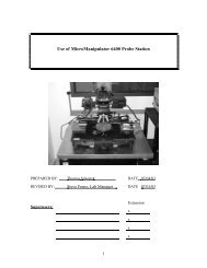
<strong>LOGITECH</strong> <strong>PM5</strong> <strong>LAPPING</strong> & <strong>POLISHING</strong> <strong>MACHINE</strong><br />
Primary contact: Chih Chen X54593<br />
PREPARED BY: Chih Chen DATE 6-15-2000<br />
Assoc. Devlp. Engr.<br />
Superusers:<br />
1<br />
Extension<br />
Hung Nguyen X57338<br />
Paulo S. Motta X45774<br />
Jeff Yao X45435<br />
<strong>NLS</strong>-<strong>030</strong>
1.0 SCOPE<br />
This document establishes the procedures for lapping and polishing of silicon, GaAs, InP<br />
and other substrates in the Nanoelectronics Laboratory.<br />
2.0 APPLICABLE DOCUMENTS<br />
Logitech logbook and maintenance log<br />
System Component Operation Manuals<br />
3.0 MATERIALS AND EQUIPMENT<br />
Logitech <strong>PM5</strong> System<br />
Precision Jig<br />
Autofeed cylinder<br />
Glass substrate<br />
Abrasive Al2O3 powders<br />
Chemcloth, 12” in diameter<br />
Polishing Cloth fir planarization<br />
Chemlox CMP solution<br />
Chemical-resist cylinder<br />
Colloidal silica<br />
Wax-Ocon-195<br />
Opticlear-<br />
Isopropyl Alcohol<br />
Gloves, cleanroom<br />
Cleanroom wipes<br />
Cleanroom mask<br />
4.0 GENERAL<br />
4.1 Logitech <strong>PM5</strong> The Logitech CMP uses abrasive slurry and chemical<br />
solution to lap and polish silicon, GaAs, InP, and other substrates in<br />
Nanoelectronics Lab.<br />
4.2 Precision Jig The unit measures the thickness of sample during lapping,<br />
and shuts down the machine automatically after lapping the programed<br />
amount of material.<br />
4.3 Machine Maintenance Maintaining a smooth and convex plate surface is<br />
needed to obtain uniform lapped surface. Maintaining a clean environment<br />
is necessary to obtain a uniform surface finish. To avoid scratches on the<br />
plate surface and exclude agglomerated particles, these steps are to be<br />
followed:<br />
2
4.3.1 Pay great attention when placing test blocks and the precision jig on<br />
the lapping plates. Never make scratches or chips on the lapping<br />
plates.<br />
4.3.2 Always clean the cylinder, stage, glass substrates and the jig<br />
thoroughly and completely whenever changing one slurry to<br />
another.<br />
4.4 Emergency Power Shut Off<br />
PROCESS PREPARATION<br />
4.4.1 Push in the "Stop" button which is located on the front of the<br />
machine.<br />
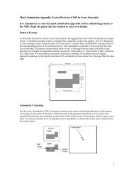
5.1 Sample Mounting Before lapping, samples must be mounted on glass substrates.<br />
Samples must be mounted on the flat side of the glass substrate which is indicated<br />
by an arrow marker “∧ “ on the edge of the glass substrate.<br />
5.1.1 Clean the glass substrates with opticlear, then alcohol, and rinse by DI<br />
water. Blow dry or wipe dry with clean room wipes.<br />
5.1.2 Place sample on the substrate facing down. Measure the thickness of the<br />
sample by the dial micrometer on the table next to the machine. See<br />
APPENDIX Ia for the operation procedure of the dial.<br />
5.1.3 Place the glass substrate on the hotplate and turn the temperature to 100<br />
set point (150 for black wax). After ~10 min or when the temperature<br />
reading is 70 to 80°C, proceed to the next step.<br />
5.1.4 Place a very small amount of wax in the center of the glass substrate with<br />
the metal spatula (stored in the tool box). For most applications the white<br />
wax, (ocon-195 in a can at the station), should be used. For very small<br />
samples or when thinning down to < 20um, the black stick wax may be<br />
used.<br />
5.1.5 Spread the wax uniformly on an area slightly larger than the sample to be<br />
mounted. Place your sample face down on the wax and slide the sample a<br />
little bit to get uniform wax thickness with the sample ultimately centered<br />
on the substrate.<br />
5.1.6 Apply pressure and/or weight on the sample if necessary. Weight should<br />
not be used on soft materials e.g., III-V compounds. Place a piece of filter<br />
paper on the sample and gently place the weight on the paper. Turn the<br />
hot plate off and wait for at least 20 minutes.<br />
3
5.1.7 Take the substrate off the hotplate. Put it on the table and let it cool<br />
down. Use wiper with Opticlear to clear the wax around the mounted<br />
sample.<br />
5.1.8 Measure the thickness of the sample after mounting. Compared with the<br />
thickness obtained in step 5.1.2, the wax thickness should be noted.<br />
5.2 Slurry Preparation In order to obtain a reasonable lapping rate and acceptable<br />
surface roughness, a proper abrasive slurry sequence should be determined in<br />
advance.<br />
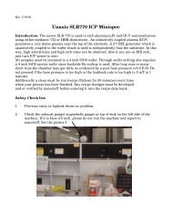
5.2.1 Check the abrasive size left in the cylinder. If the slurry in the cylinder<br />
is the size you want to use, shake it well before you use. Add more<br />
slurry if needed. The total amount of slurry should NEVER exceed<br />
the grooved line on the cylinder, as indicated by the arrow in Fig. 1.<br />
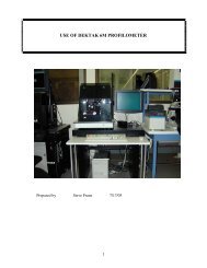
5.2.2 To make a new slurry, open the cap carefully with the screwdriver in the<br />
tool box. Untighten the four screws for the flux controller, as shown in<br />
Fig. 2. To take the valve out of the cylinder, turn the valve head<br />
counterclockwise. Dump the old slurry into the slurry waste bottle.<br />
NEVER DUMP SLURRY DOWN THE SINK. Clean the cylinder,<br />
cap, and valve thoroughly. Put the valve back when done.<br />
5.2.3 Make up Al2O3 abrasive slurry of desired particle size by mixing – ml DI<br />
water and 1.5 cups of powders in a beaker. Stir the solution entirely with<br />
the Teflon boat holder in the fume hood. Pour the slurry into the cylinder<br />
with a funnel. Add more water into cylinder until the level reaches the<br />
grooved line. However, keep slurry volume more than half of the<br />
maximum to obtain constant feeding rate.<br />
5.2.4 Tighten the cap and close the header completely by turning header<br />
clockwise. Then open it by turning it counterclockwise for about one turn.<br />
5.3 System Setup<br />
5.3.1 Check the slurry waste bottle under the machine is less than 90% full.<br />
5.3.2 Verify the vacuum exhaust at the Magnhelic gauge in fume hood is >0.<br />
5.3.3 Clean the jig thoroughly with clean room wipers and alcohol.<br />
NOTE: Always use DI water and wipers to clean plates, slurry chute, jog holder, and<br />
conditioning plates before using them, and always clean them again when switching slurry.<br />
4
6.0 PROCEDURE<br />
5.3.4 Put the cylinder on the autofeed stage, making sure that it sits on both<br />
rubber rollers appropriately.<br />
5.3.5 Remove slurry chute, jig holder, and slurry scraper assembly.<br />
5.3.6 Select the proper plate you want to use. The function of the plates is<br />
tabulated below:<br />
Plate Function Sample Materials<br />
Grooved Iron Lapping Si/Glass<br />
Glass Lapping / Polishing GaAs, InP<br />
Stainless Steel w/Pad Polishing/Planarization Oxide/Nitride/Metals<br />
Polyurethane Rough Polshing Silicon/Glass<br />
5<br />
<strong>NLS</strong>-<strong>030</strong><br />
5.3.7 Install the plate you choose by matching the three pins of the plate to the<br />
three holes on the plate stage. Be careful to keep your hands always in the<br />
groove, so that you do not pinch your fingers, as shown in Fig. 3.<br />
5.3.8 Install slurry chute, jig holder, and slurry scraper assembly, as seen in Fig.<br />
4. Please note that the wheels of jig holder never touch the plate.<br />
6.1 Conditioning Plate The purpose of this process is to make the lapping plate<br />
smooth, so that the sample can be lapped uniformly. Always use 9 μm or larger<br />
size of Al2O3 slurry for conditioning the plates.<br />
NOTE: Use iron conditioning plate for grooved iron plate; Use grooved iron<br />
conditioning plate for iron plate; Use grooved glass conditioning plate for glass plate.<br />
6.1.1 Turn on the main power of the machine.<br />
6.1.2 Turn on vacuum by flipping the toggle switch on the vacuum pump located<br />
under the machine.<br />
6.1.3 Press “POWER ON/OFF” bottom on the control panel, then press<br />
“START” bottom to rotate the plate. Increase the rotation rate to 3 rpm<br />
by pressing the “4”bottom.<br />
6.1.4 Press “ABRASIVE AUTOFEED ON/OFF” bottom, the slurry will feed<br />
automatically. Adjust the feeding rate by turning the valve on the cylinder<br />
clockwise (decrease) or counterclockwise(increase). Adjust the slurry<br />
feeder, so that the slurry drops at the position of 3 inch away from the<br />
center of the lapping plate.<br />
6.1.5 When the slurry wets about 10% area of the plate, stop the rotation by<br />
pressing “STOP” bottom.
6<br />
<strong>NLS</strong>-<strong>030</strong><br />
6.1.6 Place the right “test block” on it very carefully to avoid scratching the<br />
plate. The position of the test block is crucial. Its edge should suspend<br />
out of the plate for about 0.75 inch. Never adjust such that the outer edge<br />
of the conditioning plate is entirely inside the outer outer edge of the<br />
lapping plate. Tight jig holder. Put weight on it carefully, as seen in Fig. 5.<br />
6.1.7. Press “START”, and then the “4” bottom to slowly increase rotation<br />
speed to 2-4 rpm. Check whether the test block and weight are held by the<br />
jig holder smoothly and firmly. If not, take the weight and test block out,<br />
and then adjust the position of the jig holder. Repeat the procedure 3 to 4<br />
to get the right setup.<br />
6.1.8 Increase the speed to 70 rpm(for iron plate, and 50 rpm for glass plate).<br />
Condition the plate for 20 minutes.<br />
6.1.9 When done, press “STOP”. Take the weight and test block off. Clean the<br />
test block by DI wafer and wipers. Dry it by wipers or nitrogen blow dry.<br />
6.1.10 Then use the flatness dial to read the flatness of the test block (see<br />
appendix Ib for the instruction of how to operate the dial). Record the<br />
flatness on the logbook.<br />
6.2 Programming Lapping Thickness<br />
6.2.1 Unplug the recharge power wire for the Digital Micrometer Unit.<br />
6.2.2 Turn on the power to the SAMPLE MONITOR and the Digital<br />
micrometer, DG-925, located in the jig.<br />
6.2.3 Press “SET” on the SAMPLE MONITOR. Use “+” and “−” to enter “the<br />
thickness, in microns, to be removed”. Press “SET” again.<br />
6.3 Sample Lapping<br />
6.3.1 Put the glass substrate with sample facing up on the vacuum chuck of the<br />
jig. Plug the vacuum hose into the vacuum adapter located on the machine.<br />
Check to ensure that the glass substrate is held tightly.<br />
6.3.2 Press “START” bottom to rotate the plate. Increase the rotation rate to 3<br />
rpm by pressing the “4”bottom.<br />
6.3.3 Press the “ABRASIVE AUTOFEED ON/OFF” to feed slurry.<br />
When the slurry wets about 20% area of the plate, stop the rotation by<br />
pressing “STOP” bottom. Make sure that there is enough slurry on the<br />
area where jig sits. If a lot of time has elapsed since the plate condition.<br />
stops, run the condition block for a few minutes.<br />
6.3.4 Hold the 2 nd and 3 rd rings of the jig carefully by your fingers, as shown in<br />
Fig. 6, then flip your wrist and place it on the plate with great caution, as<br />
seen in Fig. 7. Release the second ring of the jig after the jig is securely on<br />
the lapping plate.
7<br />
<strong>NLS</strong>-<strong>030</strong><br />
6.3.5 Check if the wheels of the jig holder are in the right position, i.e. match the<br />
first ring of the jig, as seen in Fig. 8. Never move the jig around on the<br />
plate, while the sample is down. Make all needed adjustments while<br />
holding the 2 nd and 3 rd rings together.<br />
6.3.6 Check if the reading on DG-925 is zero. If not, press “RESET”.<br />
If it is still not zero, more weight/pressure may be needed.<br />
6.3.7 If weight/pressure adjustment is needed, use one of your hands lifting up<br />
the second ring, and then use the other hand adjusting the weight by<br />
rotating the big screw, as illustrated in Fig. 9. Always lift up sample when<br />
adjust weight/ pressure. Turn it clockwise to increase weight or<br />
counterclockwise to reduce weight.<br />
6.3.8 Press “START” and then “ABRASIVE AUTOFEED ON/OFF” to feed<br />
slurry. Increase the rotation rate to 2-4 rpm by pressing the “4”bottom.<br />
6.3.9 Turn on slurry sensor to monitor slurry feeding, which locates under the<br />
cylinder head. When the slurry feeding rate is too slow, it will shut down<br />
the machine to protect sample from being destroyed.<br />
6.3.10 Examine the reading on DG-925. If it is stable, press “RUN” on Sample<br />
Monitor. Then increase the speed to 25 - 35 rpm.<br />
6.3.11 Always close the lid during lapping. In particular, for InP, phosphine<br />
comes out during lapping and polishing.<br />
6.3.12 Check the jig position once in a while. The jig may separate from the jig<br />
holder.<br />
6.4 Lapping Completion<br />
6.4.1 The machine shuts down automatically once the set thickness is removed.<br />
Press power off to silence the beeping.<br />
6.4.2 Turn off the digital micrometer and the sample monitor.<br />
6.4.3 Hold the 2 nd and 3 rd rings of the jig by your fingers. Take it out very<br />
carefully. Flip it over and place it on the plastic jig rack on<br />
the table, as shown in Fig. 6.<br />
6.4.4 Unplug the vacuum hose from the adapter. Wait for about 20 seconds.<br />
Then take the glass substrate out.<br />
6.4.5 If no polishing needed, clean the machine and the jig thoroughly.<br />
6.4.6 Turn off the main power for the machine<br />
6.4.7 Turn off the power for pump.
7.0 <strong>POLISHING</strong><br />
6.4.8 Label the cylinder with the slurry size and the date made.<br />
8<br />
<strong>NLS</strong>-<strong>030</strong><br />
6.4.9 Recharge the battery of the Digital Micrometer Unit by plug in the 9V DC<br />
power adapter.<br />
6.4.10 Fill out the logbook completely.<br />
6.4.11 If silicon carbon or cerium oxide abrasive is used, make a note on the<br />
slurry waste container.<br />
6.4.12 If polishing is required, go to section 7.0. If not, go to Section 9.0<br />
for sample removal.<br />
When a very smooth and reflective surface are required (Ra
7.1.5 Repeat procedures 5.3.1 to 5.3.8 to setup polishing system.<br />
7.1.6 Setting up the Sweeping Arm as follows to achieve better surface<br />
finishing.<br />
7.1.6.1 Press Sweeping Arm button on the LCD screen.<br />
9<br />
<strong>NLS</strong>-<strong>030</strong><br />
7.1.6.2 Choose SYSChecks button. The screen should show “System<br />
Checks in Progress”.<br />
7.1.6.3 Press Continue button when the system checks are done.<br />
7.1.6.4 Press Edit button.<br />
7.1.6.5 Set Inner Sweep Limit by using “ + “ and “–“ buttons.<br />
The lower the number is; the wider the arm sweeps.<br />
7.1.6.6 Choose Next button to go to Outer Sweep limit setting. Adjust<br />
range by using “ + “ and “–“ buttons, so that the sample always<br />
stays on lapping plate during sweeping. The higher the number is,<br />
the wider the arm sweeps.<br />
7.1.6.7 Press Next button to go to sweep speed setting. Set the speed to<br />
approximately 70%.<br />
7.1.6.8 Press Exit button to exit the Sweeping Arm setting.<br />
7.1.7 Follow the procedure from 6.3.1 to 6.3.12. Skip procedures for using the<br />
digital micrometer (6.3.6, 6.3.8, and 6.3.9).<br />
7.1.8 Press Sweeping Arm button to start sweeping. Adjust the sweep amplitude<br />
and speed if needed.<br />
7.1.9 Press “Exit” button when the polishing is done.<br />
7.1.10 For the purpose of disposing the slurry waste, make a note on the sheet<br />
attached to the waste container when colloidal silica or Chemlox solution<br />
is used.<br />
7.1.11 Clean the plate and the polishing pad completely. Leave a note on the<br />
polishing plate underside for the materials lapped and polishing solution<br />
used.<br />
7.1.12 Clean the machine and jig thoroughly.<br />
7.1.13 Fill out another record in the logbook for polishing.<br />
7.1.14 Go to Section 9.0 for sample removal.
7.2 Rough Polshing by Polyurethane Plate<br />
8.0 Planarization:<br />
Polyurethane plate with colloidal silica solution can be employed to coarsely<br />
Polish silicon or glass.<br />
7.2.1 Conditioning plate.<br />
Before polishing the plate, the plate needs to be conditioned by the<br />
stainless steel test block with blades.<br />
7.2.1.1 Follow the procedures from 5.3.1 to 5.3.8 to setup polishing<br />
system using the Polyurethane plate with the test block.<br />
10<br />
<strong>NLS</strong>-<strong>030</strong><br />
7.2.1.2 Spread water on the plate by a wash bottle. Make sure that the<br />
amount of water is enough to wet all the surface of the plate.<br />
7.2.1.3 Put the test block on the plate, and hold it by jig holder.<br />
7.2.1.4 Spread water on the plate by a bottle. Make sure that water wet<br />
all the surface all the time during the conditioning process.<br />
7.2.1.5 Turn on the main power of the machine.<br />
7.2.1.6 Press “POWER ON/OFF” bottom on the control panel, then<br />
press “START” bottom to rotate the plate. Increase the rotation<br />
rate to 3 rpm by pressing the “4”bottom.<br />
7.2.1.7 Check whether the test block and weight are held by the jig<br />
holder smoothly and firmly. If not, take the weight and test<br />
block out, and then adjust the position of the jig holder<br />
7.2.1.8 Increase the speed to 35 rpm. Condition the plate for 3 to 5<br />
minutes. Spread DI water constantly to keep the surface of the<br />
plate wet.<br />
7.2.1.9 When done, press “STOP”. Take the test block off. Clean the<br />
test block by DI wafer and wipers. Dry it by wipers or nitrogen<br />
blow dry.<br />
7.2.2 Rough Polishing<br />
Use colloidal silica for polishing silicon; while cerium oxide for<br />
polishing glass.<br />
7.2.2.1 Select the proper polishing solution. Follow the procedure in<br />
Section 7.1.
Oxide, nitride, or metals can be planarized by the following procedure:<br />
9.0 SAMPLE REMOVAL<br />
8.1 Use the stainless steel lapping plate with PANMA 12” DP-PAN<br />
polishing cloth.<br />
8.2 Following the procedure in Section 7.1. Use colloidal silica<br />
for planarization.<br />
Samples may be removed either by melting or dissolving method.<br />
11<br />
<strong>NLS</strong>-<strong>030</strong><br />
9.1 Melting method When SILICON samples are thicker than 200 μm, the sample<br />
may be taken off the glass plate by melting the wax on a hotplate.<br />
9.1.1 Place glass substrate on the hotplate with sample facing up. Turn the<br />
temperature to 110 set point for white wax ( 160 for black wax).<br />
9.1.2 Wait for about 10 minutes. Use tweezers to push the edge of the sample<br />
to slide it off the glass substrate.<br />
9.1.3 Clean the sample and the substrate by immersing them into the Opticlear<br />
solution stored in the fume hood next to the machine, followed by<br />
alcohol and DI water rinse.<br />
9.2 Dissolving method For brittle materials, such as thinner Si samples, GaAs, or<br />
InP, it is recommended to use the Opticlear solution to dissolve the wax laterally.<br />
9.2.1 Use the beaker labeled “Opticlear” in the fume hood next to the machine.<br />
Place the glass substrate on the teflon ring in the beaker with sample<br />
facing down. Make sure that the sample does not touch the teflon ring.<br />
9.2.2 Make sure that there is enough Opticlear solution, so that the solution<br />
covers the sample. Cover the beaker with a petri-dish lid.<br />
9.2.3 The sample will drop into the solution when done. It will take few to tens<br />
of hours, depending on the sample size.<br />
9.2.4 Clean the sample and glass substrate by alcohol and DI water.
Valve<br />
Cap<br />
Max<br />
Fig. 1 The cylinder<br />
Groove<br />
12<br />
Fig. 2 Cylinder cleaning<br />
Fig. 3 Install a lapping plate on the machine. Fig. 4 System setup.<br />
Weight<br />
Lapping<br />
plate<br />
Condititon<br />
plate<br />
Fig. 5 Conditioning lapping plate.<br />
Cylinder<br />
Slurry feeder<br />
<strong>NLS</strong>-<strong>030</strong><br />
Rubber<br />
Cleaning<br />
pad<br />
Jig holder
Fig. 6 Holding the jig by press the 2 nd<br />
and 3 rd rings together.<br />
Fig. 8<br />
2 nd ring<br />
3 rd ring<br />
Fig. 8 The proper position of the<br />
jig on the lapping plate<br />
13<br />
<strong>NLS</strong>-<strong>030</strong><br />
Fig. 7 Placing the jig on the lapping plate<br />
Fig. 9 Adjusting the weight<br />
on sample
APPENDIX I<br />
a. Operation Procedure for Measuring Sample Thickness Using a Dial<br />
14<br />
<strong>NLS</strong>-<strong>030</strong><br />
a.1 Lift the tip up carefully by pulling the knob on the dial. Place the glass<br />
substrate with sample on it below the tip, so that when the tip is released, it<br />
lands on glass substrate, not on sample.<br />
a.2 Rotate the outer ring of the dial. Zero the height by matching the outer<br />
indicator to zero.<br />
a.3 Pull the tip up again and move the glass substrate, so that the sample is<br />
below the tip. Release the tip very slowly and carefully. Read the outer<br />
scale for thickness of the sample. The smallest unit in the outer scale<br />
represents ten microns.<br />
b. Operation Procedure for Measuring Surface Flatness of a Conditioned Lapping<br />
Plate.<br />
b.1 Move the flatness dial slightly around the flat standard to seat the tip. Zero<br />
the dial if needed.<br />
b.2 Place the test block up side down on the weight.<br />
b.3 Use one finger to raise the tip by lightly pressing the handle above the<br />
dial before taking the dial off the standard. Take it off from the standard.<br />
Place it on the conditioned plate. Release the handle very carefully until<br />
the probe touches the plate. Move it around and read the flatness. The<br />
smallest scale on the dial is two microns. The smallest scale on the outer<br />
dial is two microns.