1 Polypro Acid Wet Bench UCLA Nanolab Yellow Room Primary ...
1 Polypro Acid Wet Bench UCLA Nanolab Yellow Room Primary ...
1 Polypro Acid Wet Bench UCLA Nanolab Yellow Room Primary ...

You also want an ePaper? Increase the reach of your titles
YUMPU automatically turns print PDFs into web optimized ePapers that Google loves.
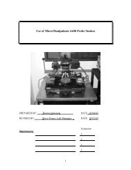
<strong>Polypro</strong> <strong>Acid</strong> <strong>Wet</strong> <strong>Bench</strong><br />
<strong>UCLA</strong> <strong>Nanolab</strong> <strong>Yellow</strong> <strong>Room</strong><br />
<strong>Primary</strong> contacts: Hoc Ngo, Tom Lee<br />
QuickTime and a<br />
Photo - JPEG decompressor<br />
are needed to see this picture.<br />
PREPARED BY: Steve Franz DATE Rev 2/20/03<br />
1
1.0 SCOPE<br />
PolyPro <strong>Acid</strong> <strong>Wet</strong> <strong>Bench</strong><br />
This document establishes the procedures for using the polypro acid wet bench located in the <strong>Nanolab</strong><br />
<strong>Yellow</strong> <strong>Room</strong>. Only trained users may use this bench. Additional hot plates, ultrasonic cleaners,<br />
plating tanks etc are NOT to be used at this fume hood without permission from the lab staff.<br />
Unused beakers are NOT to be stored at the sink. All baths should be covered when not in use.<br />
Chemical -proof visor, apron and gloves must be worn whenever pouring chemicals. All chemicals<br />
must be labeled with chemical name, user, phone #, date & time started and finished.<br />
2.0 APPLICABLE DOCUMENTS<br />
Appropriate log books, MSDS sheets for chemicals used.<br />
Operating Instructions for Modutek Dump Rinsers, Controllers and Timers<br />
3.0 MATERIALS AND EQUIPMENT<br />
<strong>Polypro</strong> wet bench, appropriate chemicals and chemical beakers (optional).<br />
4.0 DECK LAYOUT<br />
The polypro wet bench located in the <strong>Nanolab</strong> <strong>Yellow</strong> <strong>Room</strong>, is designated for acid and base cleaning<br />
and etching. It is not intended for solvent cleans, HMDS or work with flammable chemicals. Use the<br />
stainless steel solvent sink for these operations. Observe all warnings and cautions when using this bench.<br />
The deck layout is shown in Fig 1 and is described below:<br />
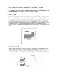
Fig 1. <strong>Polypro</strong> <strong>Wet</strong> <strong>Bench</strong> for <strong>Acid</strong> Processing<br />
A, F 2 temperature controlled heated baths with drains, level sensors and over-temperature protection. Bath A is<br />
designated for organic clean eg piranha or ammonium hydroxide solutions. Bath F is designated for<br />
inorganic strips such as HCL/ peroxide cleans. Liquid levels must be filled past the white/black line and<br />
BOTH drains must be closed. A dedicated log book for each hot pot is kept at the fume hood and must be<br />
filled out for EACH use as well as dumps and fills. Always label the cover with pot’s contents.<br />
2
B, E 2 beaker tanks. Do NOT pour chemicals directly into tank. Tanks may be used for any unheated soaking in<br />
acids or bases. Do NOT use these tanks for solvents.<br />
C A time-controlled hot plate for etching or cleaning (No Solvents). Temperature is set at the hot plate and a<br />
magnetic stirrer control is also located at the hot plate. The cover MUST BE REMOVED during heating or<br />
it may melt. An integrated timer shuts off the hot plate after 4 hours.<br />
D A set of 2 aspirators used only in emergency or for draining water after rinsing out tanks. City water is used<br />
to create suction and aspirate the solution to the drain therefore chemicals must NEVER be aspirated.<br />
G Gooseneck sink for rinsing and filling with DI water. (Note that ALL water is DI except at the aspirator.)<br />
There are 2 valves for the gooseneck, one at the neck itself, which should be adjusted to get the desired flow<br />
and another on the front of the fume hood used as an on/off valve.<br />
H, N 2 Sets of N2 blow guns and DI rinse guns. Both guns should recoil back into the recessed wells when done.<br />
Note that DI water resistivity and temperature may be monitored from the headcase resistivity display (see<br />
later in spec).<br />
I, M 2-2 stage cascade DI water rinsers with N2 bubblers in the 1st stage. Substrates should always begin in the<br />
bubbler (dirty) tank and finish in the non-bubbler (clean) tank. The correct order is tank 1 and then tank 2.<br />
On/off for both the water flow and bubbler is located in the headcase. USE ONLY THE AMOUNT OF<br />
WATER ABSOLUTELY NEEDED. Using more than required or "forgetting to turn it off" can drain our<br />
storage tank and shut down the lab. Each cascade can accommodate up to a 6 inch wafer cassette.<br />
J, L A set of 2 DI water dump rinsers. Rinsers are preset to 5 cycles but are programmable. See lab staff for<br />
special applications requiring changes. Each rinser can hold up to one 6 inch cassette.<br />
K Hydrofluoric acid etch tank. EXTREME CAUTION is required in using this tank which is unheated but<br />
connected to the HF drain. Always label the tank with the concentration being used ie 10:1, 6:1 etc. BOE<br />
may also be used in this tank and must be so labeled. MAKE SURE BOTH DRAIN VALVES ARE<br />
CLOSED BEFORE POURING CHEMICALS. The drain for this tank is controlled by the process<br />
controller (item A in Fig 3.). Fill out the log book after EACH use OR whenever refilling the tank.<br />
O Set of 3 manual drain and waste bottles for hot bath 1 and 2 and the HF tank. Extreme caution must be<br />
exercised when draining chemicals ie empty bottle in place, solution cooled down and manual valve opened<br />
slowly. Use a prelabelled waste bottle (labels are provided in the yellow room) and always watch while<br />
draining and shut off all drain valves when done.<br />
5.0 HEADCASE AND MODULE CONTROLS<br />
All of the controllers, timers and electronics are located in the head case above the fume hood. Additionally, the<br />
magnehelic gauge to verify fume hood exhaust is located at the extreme right of the headcase. You must always<br />
verify that the gauge's needle is in the safe zone BEFORE using the hood.<br />
3
5.1 Left Side Headcase (refer to Fig 2).<br />
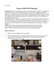
Fig 2 Left Side Headcase and Controls for polypro acid sink<br />
A Emergency Power Shut Off: Turns off power to entire sink.<br />
B Power Light Indicator: Lit if power is active to the hood.<br />
C Independent programmable timer for timing various processes. Timer may be programmed up to 99 minutes<br />
and will give an audible alert when set point is reached. See more detailed explanation in timer section.<br />
D Temperature controller for heated tank (A in Fig 1). See separate section for its operation. An integrated<br />
timer will shut off the timer after 4 hours. Additionally a level sensor will shut down the power if the liquid<br />
level is too low. The tank may also be drained using the controller. ALWAYS TURN OFF POWER<br />
WHEN FINISHED PROCESSING.<br />
E Top is pneumatic cascade water switch (clockwise for on) and its indicator light above it. Bottom is a<br />
pneumatic bubbler switch with its indicator light above it. These controls are associated with the<br />
rinser/bubbler labeled I in Fig 1. Turn off DI water as soon as you finish.<br />
F Dump rinser controller for item J in Fig 1 pre-programmed for 5 dump cycles. See separate section for<br />
controller operation.<br />
G Light switch (top): Turns on yellow lights for entire fume hood. Turn lights off when not in use. Aspirator<br />
(bottom) (D in Fig 1): To be used only in emergency or for aspirating water eg rinsing tanks.<br />
4
5.2 Center Headcase (refer to Fig 3).<br />
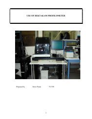
Fig 3 Center Headcase and Controls for <strong>Polypro</strong> sink<br />
A HF tank drain valve and indicator. Clockwise opens valve. Make sure HF-compatible labeled empty bottle<br />
is in place, and slowly open manual valve to drain liquid. DO NOT LEAVE UNTIL THE SOLUTION IS<br />
TRANSFERRED TO A PRELABELED WASTE BOTTLE AND CLOSE ALL DRAIN VALVES<br />
IMMEDIATELY AFTER FINISHING. Remove and store waste bottle in designated area.<br />
B Hot plate timer (C in Fig 1) automatically shuts off after 4 hours. Controls time only, temperature is<br />
controlled directly at hot plate. Stirrer is also controlled directly at hot plate. CAUTION: KEEP POLYPRO<br />
COVER OFF WHEN USING HOT PLATE AND TURN OFF HOT PLATE WHEN FINISHED.<br />
C Set of sonoalerts associated with various controllers. Press the appropriate silence button when alarm<br />
sounds.<br />
D Set of 2 stand alone timers for timing various processes. Timers may be programmed up to 99 minutes and<br />
will give an audible alert when set point is reached. See more detailed explanation in timer section.<br />
E 2nd dump rinse controller for rinser L in Fig 1. Dump rinser is pre-programmed for 5 cycles and can<br />
accommodate up to one 6 inch wafer cassette.<br />
5
5.3 Right Side Headcase (refer to Fig 4).<br />
Fig 4 Right Side Headcase and Controls<br />
A Right aspirator (D in Fig 1): To be used only in emergency or for aspirating water.<br />
B Temperature controller for heated tank (F in Fig 1). See separate section for its operation. An integrated<br />
timer will shut off the timer after 4 hours. Additionally a level sensor will shut down the power if the liquid<br />
level is too low. The tank may also be drained using the controller. ALWAYS TURN OFF POWER<br />
WHEN FINISHED PROCESSING. Fill out the log book after each use and whenever the chemical is<br />
changed.<br />
C Cascade water switch and indicator (top) and bubbler switch and indicator (bottom). Used to control<br />
cascade rinse, M in Fig 1. Turn off DI water as soon as you finish.<br />
D DI temperature/resistivity water display. Press "Display" button to toggle display between temperature and<br />
resistivity. Typically resistivity should be greater than 8 M Ohm-cm. If it is too low let DI water run for no<br />
longer than 2 or 3 minutes. Our system has a single channel (measuring point) at the sink input so ignore<br />
channel 2. Press the bottom return/sil button if an alarm sounds. If alarm continues to sound, report problem<br />
to lab staff.<br />
E Headcase nitrogen purge. This is not adjustable by sink users but should be reported to lab staff if flow is<br />
outside of indicated (mid-level) range.<br />
F Magnehelic vacuum gauge. This gauge MUST be checked that the needle is in the acceptable range<br />
BEFORE each use of the fume hood.<br />
6
6.0 SET UP AND OPERATION OF INDIVIDUAL CONTROLLERS AND MODULES<br />
The Modutek C1115a is used only to control the heated baths (A & F in Fig 1) in the acid wet bench. Refer to Fig 5<br />
for the various control buttons.<br />
6.1 Operation of Hot Bath Controller (Modutek C1115a)<br />
Fig 5 Heated Bath Controller<br />
6.1.1 Setting up and using the bath:<br />
1 Verify the drain valves are closed and that the bath is filled to the upper white region with the<br />
correct chemical: piranha or organic clean in bath A or inorganic clean (eg HCl/H2O2) in bath F<br />
(Fig 1).<br />
2 Press and hold the "Power" key on the controller until the display light comes on. System comes<br />
up in the hold mode for safety reasons.<br />
3 Press "Reset" key. System goes into normal mode unless there is an alarm condition.<br />
4 If the stored temperature in memory is the desired temperature, the "Timer" key may be used to<br />
start the countdown, otherwise contact lab staff or superuser to make a change.<br />
7
5 Pressing the "Timer" key a 2nd time freezes the count and a 3rd press restarts it. The timer will<br />
start alarming a programmable prewarning and will keep counting past the set time so that the total<br />
elapsed time is monitored.<br />
6 Superuser may change the temperature by pressing "Prog". "CODE" flashes on the display. Enter<br />
the access code by using the arrow keys and press "Prog" again. NOTE: only superusers or lab<br />
staff can perform this operation.<br />
7 Each time the "Prog" key is pressed, a different parameter is displayed: CS-clock setpoint (time<br />
duration), PA-prewarn offset, and PS-Process Setpoint (temperature). The arrow keys are used to<br />
change the value of each and the range for each is:<br />
CS Clock Setpoint 00:00 to 99:59 Min:Sec<br />
PA Prewarn Offset 00:00 to 00:59 Seconds<br />
PS Process Setpoint 00.00 to 199.9 Degress C<br />
Press "Prog" after each value change to go to the next parameter.<br />
CAUTION: There are 12 other parameters which MUST NOT be changed as they can cause<br />
system failure.<br />
8 Press "Reset" to return to the normal mode<br />
9 Do NOT use the Save key as this will make your changes the default changes. Lab staff will put the<br />
appropriate default values in the EEPROM. In this way if a mistake is made, turning the power on<br />
and off will call up the default values.<br />
10 To drain the solution from the tank, make sure an empty waste bottle is under the spigot and that<br />
the solution is adequately cooled (usually below 40 C). Press “Drain” twice to open the valve. Go<br />
to the manual valve and slowly open it. After the bath is drained close the manual and controller<br />
drain immediately.<br />
11 Fill out the log book after each use OR whenever changing the bath solution.<br />
6.1.2 Additional keys and their use:<br />
HOLD Timer freezes and the heater is disabled<br />
VIEW Displays process setpoint and timer preset<br />
SAVE/SIL Save works in the Program mode and is to be used ONLY by staff<br />
In normal mode, it silences the alarm<br />
DRAIN Works in conjunction with the manual valve at left side of sink and opens drain<br />
up if solution is below preprogrammed dr setting.<br />
6.1.3 Alarms:<br />
SYSTEM A system malfunction such as the EEPROM save routine.<br />
SENSOR An open circuit for thermocouple is detected, the heater is shut off and the<br />
display flashes "OP" for open sensor.<br />
H LIMIT A dangerous overtemperature condition is detected and the heater is shut down.<br />
L TEMP Low temperature alarm. LO flashes on the display.<br />
L LEVEL Low liquid level sensor. LL is flashed and the heater is turned off.<br />
6.2 Operation of Timers (Modutek T16a)<br />
There are 3 stand-alone timers (C & D in Figs 2 & 3). All are Modutek T16a in the acid wet bench. Refer to Fig 6<br />
below.<br />
8
Fig 6 Stand Alone Timers<br />
6.2.1 Using and setting up the timers.<br />
1 Press "start" to begin the timer countdown. The pre-programmed time is shown in the<br />
display. The timer goes into the run mode and the display counts down.<br />
2 To change the time, enter the program mode by holding the "Stop/Reset" key and<br />
pressing "Start". The program indicator light should come on. While in the Program mode<br />
the "start" key is used to toggle between the time and pre-alarm setpoints:<br />
CS Clock Set point 0:00 to 99:59 Min:Sec<br />
PA Pre-alarm 0:00 to 0:59 Seconds<br />
3 Use the arrow keys to adjust the desired times for each function<br />
4 Press "Reset" key to exit the program mode.<br />
6.2.2 Additional timer features.<br />
The "start" key may be used as an audio silencer without stopping the timer.<br />
The pre-alarm sounds an audio tone with a 50/50 duty cycle for a second; the setpoint alarm is a<br />
continuous tone which also causes the display to flash.<br />
6.3 Operation of Dump Rinse Controllers (Modutek C15)<br />
Dump rinsers J & L in Fig 1 are controlled by dump rinse controllers F & E in Figs 2 & 3 and its operation is<br />
described below (refer to Fig 7).<br />
9
6.3.1 Keypad Operation<br />
Start- Activates the rinser for the number of pre-programmed cycles shown in the display. It<br />
continues running the system if it is in the HOLD mode.<br />
Stop/Reset- Puts system in HOLD if it is still running; resets controller if it is in Hold; exits<br />
program mode and resets controller in PROGRAM mode.<br />
Prog- 1st key press places system in PROGRAM mode. An access code is needed to proceed.<br />
Only trained authorized users are given this code. After entering access code, pressing 'Prog" will<br />
scroll through the various parameters. Arrow keys are used to increase or decrease the displayed<br />
parameter.<br />
Open- This key is used to manually dump the tank. Press the "Reset" key twice to force the dump<br />
door closed again.<br />
6.3.2 Programming<br />
Programming will be done by the lab staff or appropriate superuser. Adjustments to fill or dump<br />
time and the number of cycles should be referred to the lab staff. NOTE: WHEN USING DUMP<br />
RINSERS VERIFY THAT THE WAFER AND CASSETTE ARE COMPLETELY COVERED<br />
BY WATER BEFORE WATER IS DUMPED.<br />
Fig 7 Modutek C15 Dump Rinse Controllers<br />
10