anisotropic plasticity and failure prediction in wood ... - ANSYS Users
anisotropic plasticity and failure prediction in wood ... - ANSYS Users
anisotropic plasticity and failure prediction in wood ... - ANSYS Users

You also want an ePaper? Increase the reach of your titles
YUMPU automatically turns print PDFs into web optimized ePapers that Google loves.
ANISOTROPIC PLASTICITY AND FAILURE PREDICTION IN WOOD COMPOSI...<br />
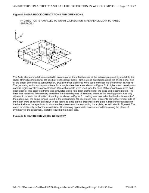
Figure 5. SHEAR BLOCK ORIENTATIONS AND DIMENSIONS.<br />
(Y-DIRECTION IS PARALLEL-TO-GRAIN, Z-DIRECTION IS PERPENDICULAR TO PANEL<br />
SURFACE.)<br />
The f<strong>in</strong>ite element model was created to determ<strong>in</strong>e: a) the effectiveness of the <strong>anisotropic</strong> <strong>plasticity</strong> model, b) the<br />
shear strength constants for the Weibull weakest l<strong>in</strong>k theory, c) the stress distribution along the shear plane, <strong>and</strong><br />
d) the effect of the stress concentration. SOLID45 brick elements were used to model the shear block <strong>in</strong> <strong>ANSYS</strong>.<br />
The geometry <strong>and</strong> boundary conditions for a s<strong>in</strong>gle shear block are shown <strong>in</strong> Figure 6. A higher mesh density was<br />
used <strong>in</strong> regions of stress concentrations. Six such models were used (one for each of the shear block sizes <strong>and</strong><br />
orientations). The steel test frame was simulated us<strong>in</strong>g rigid brick elements for the base <strong>and</strong> load<strong>in</strong>g platen. The<br />
base was restricted from mov<strong>in</strong>g <strong>in</strong> each of the three degrees of freedom, whereas the load<strong>in</strong>g platen was only<br />
allowed to move <strong>in</strong> the direction of load<strong>in</strong>g, as shown <strong>in</strong> Figure 6. Load<strong>in</strong>g was controlled by the displacement of<br />
the platen over the same ranges found <strong>in</strong> the experiments for each block type. Elements along the vertical side of<br />
the notch were on rollers, as shown <strong>in</strong> the figure, to simulate the presence of the platen. Rollers were placed on<br />
the back side of the specimen to simulate the presence of the support<strong>in</strong>g back plate, as <strong>in</strong>dicated <strong>in</strong> Figure 6. The<br />
entire model is only half of the actual shear block (us<strong>in</strong>g appropriate boundary conditions along the plane of<br />
symmetry of the specimen), thereby reduc<strong>in</strong>g the model size.<br />
Figure 6. SHEAR BLOCK MODEL GEOMETRY<br />
file://C:\Documents%20<strong>and</strong>%20Sett<strong>in</strong>gs\beh\Local%20Sett<strong>in</strong>gs\Temp\~hhC936.htm<br />
Page 12 of 22<br />
7/9/2002