anisotropic plasticity and failure prediction in wood ... - ANSYS Users
anisotropic plasticity and failure prediction in wood ... - ANSYS Users
anisotropic plasticity and failure prediction in wood ... - ANSYS Users

Create successful ePaper yourself
Turn your PDF publications into a flip-book with our unique Google optimized e-Paper software.
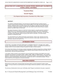
ANISOTROPIC PLASTICITY AND FAILURE PREDICTION IN WOOD COMPOSI...<br />
The unbolted end of the member was restricted from displacements <strong>in</strong> the Y-direction by apply<strong>in</strong>g a zerodisplacement<br />
boundary along the plane normal to the Y-direction as shown <strong>in</strong> Figure 9. The two planes of<br />
symmetry <strong>in</strong> the <strong>wood</strong> <strong>and</strong> dowel were modeled with zero-displacement boundary conditions <strong>in</strong> the planes normal<br />
to the X- <strong>and</strong> Z-directions. Displacements were applied to the end of the bolt to simulate the experimental<br />
displacement-controlled conditions. These displacements were fixed <strong>in</strong> the Y-direction towards the bolted end of<br />
<strong>wood</strong> member.<br />
One model was used for each connection geometry <strong>and</strong> set of material properties. The solution was non-l<strong>in</strong>ear<br />
due to material non-l<strong>in</strong>earity <strong>and</strong> the iterations required to enforce the contact compatibility. Displacements to the<br />
end of the dowel were imposed <strong>in</strong> small steps to assist <strong>in</strong> convergence. Data was saved for each step.<br />
Convergence was not typically possible beyond total displacement of roughly 2.5 mm (0.1 <strong>in</strong>ch) even though<br />
experimental displacements were much larger. Enough <strong>in</strong>formation about the performance of the connection<br />
could be determ<strong>in</strong>ed, however, as will be shown shortly.<br />
CASE II - Results<br />
Load-displacement curves from the experiments <strong>and</strong> from <strong>ANSYS</strong> are shown <strong>in</strong> Figure 10 for load<strong>in</strong>g parallel-to<br />
<strong>and</strong> perpendicular-to-gra<strong>in</strong>, respectively. Specimens with 9.5 mm (3/8 <strong>in</strong>ch) <strong>and</strong> 19 mm (3/4 <strong>in</strong>ch) diameter, d,<br />
bolts are discussed here. Two end distances, 2d <strong>and</strong> 4d were chosen to force a change <strong>in</strong> the mode of <strong>failure</strong>.<br />
Values of maximum load, maximum displacement along with the mode <strong>failure</strong> are listed <strong>in</strong> Tables 7, 8 <strong>and</strong> 9, each<br />
correspond<strong>in</strong>g to the direction of load<strong>in</strong>g.<br />
Figure 10. LOAD-DISPLACEMENT CURVES FOR SINGLE-BOLT CONNECTIONS LOADED<br />
(A) PARALLEL-TO-GRAIN, AND (B) PERPENDICULAR-TO-GRAIN. DARK LINE IS RESULT<br />
FROM <strong>ANSYS</strong><br />
file://C:\Documents%20<strong>and</strong>%20Sett<strong>in</strong>gs\beh\Local%20Sett<strong>in</strong>gs\Temp\~hhC936.htm<br />
Page 18 of 22<br />
7/9/2002