LAS SPECIFICATION VERSION 1.4 – R11 - asprs
LAS SPECIFICATION VERSION 1.4 – R11 - asprs
LAS SPECIFICATION VERSION 1.4 – R11 - asprs

Create successful ePaper yourself
Turn your PDF publications into a flip-book with our unique Google optimized e-Paper software.
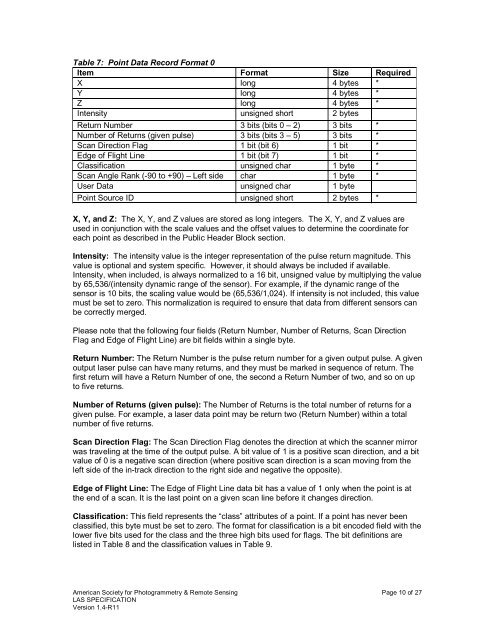
Table 7: Point Data Record Format 0<br />
Item Format Size Required<br />
X long 4 bytes *<br />
Y long 4 bytes *<br />
Z long 4 bytes *<br />
Intensity unsigned short 2 bytes<br />
Return Number 3 bits (bits 0 <strong>–</strong> 2) 3 bits *<br />
Number of Returns (given pulse) 3 bits (bits 3 <strong>–</strong> 5) 3 bits *<br />
Scan Direction Flag 1 bit (bit 6) 1 bit *<br />
Edge of Flight Line 1 bit (bit 7) 1 bit *<br />
Classification unsigned char 1 byte *<br />
Scan Angle Rank (-90 to +90) <strong>–</strong> Left side char 1 byte *<br />
User Data unsigned char 1 byte<br />
Point Source ID unsigned short 2 bytes *<br />
X, Y, and Z: The X, Y, and Z values are stored as long integers. The X, Y, and Z values are<br />
used in conjunction with the scale values and the offset values to determine the coordinate for<br />
each point as described in the Public Header Block section.<br />
Intensity: The intensity value is the integer representation of the pulse return magnitude. This<br />
value is optional and system specific. However, it should always be included if available.<br />
Intensity, when included, is always normalized to a 16 bit, unsigned value by multiplying the value<br />
by 65,536/(intensity dynamic range of the sensor). For example, if the dynamic range of the<br />
sensor is 10 bits, the scaling value would be (65,536/1,024). If intensity is not included, this value<br />
must be set to zero. This normalization is required to ensure that data from different sensors can<br />
be correctly merged.<br />
Please note that the following four fields (Return Number, Number of Returns, Scan Direction<br />
Flag and Edge of Flight Line) are bit fields within a single byte.<br />
Return Number: The Return Number is the pulse return number for a given output pulse. A given<br />
output laser pulse can have many returns, and they must be marked in sequence of return. The<br />
first return will have a Return Number of one, the second a Return Number of two, and so on up<br />
to five returns.<br />
Number of Returns (given pulse): The Number of Returns is the total number of returns for a<br />
given pulse. For example, a laser data point may be return two (Return Number) within a total<br />
number of five returns.<br />
Scan Direction Flag: The Scan Direction Flag denotes the direction at which the scanner mirror<br />
was traveling at the time of the output pulse. A bit value of 1 is a positive scan direction, and a bit<br />
value of 0 is a negative scan direction (where positive scan direction is a scan moving from the<br />
left side of the in-track direction to the right side and negative the opposite).<br />
Edge of Flight Line: The Edge of Flight Line data bit has a value of 1 only when the point is at<br />
the end of a scan. It is the last point on a given scan line before it changes direction.<br />
Classification: This field represents the “class” attributes of a point. If a point has never been<br />
classified, this byte must be set to zero. The format for classification is a bit encoded field with the<br />
lower five bits used for the class and the three high bits used for flags. The bit definitions are<br />
listed in Table 8 and the classification values in Table 9.<br />
American Society for Photogrammetry & Remote Sensing Page 10 of 27<br />
<strong>LAS</strong> <strong>SPECIFICATION</strong><br />
Version <strong>1.4</strong>-<strong>R11</strong>