LAS SPECIFICATION VERSION 1.4 – R11 - asprs
LAS SPECIFICATION VERSION 1.4 – R11 - asprs
LAS SPECIFICATION VERSION 1.4 – R11 - asprs

You also want an ePaper? Increase the reach of your titles
YUMPU automatically turns print PDFs into web optimized ePapers that Google loves.
Scanner Channel: Scanner Channel is used to indicate the channel (scanner head) of a multichannel<br />
system. Channel 0 is used for single scanner systems. Up to four channels are<br />
supported (0-3).<br />
Scan Direction Flag: The Scan Direction Flag denotes the direction at which the scanner mirror<br />
was traveling at the time of the output pulse. A bit value of 1 is a positive scan direction, and a bit<br />
value of 0 is a negative scan direction (where positive scan direction is a scan moving from the<br />
left side of the in-track direction to the right side and negative the opposite).<br />
Edge of Flight Line: The Edge of Flight Line data bit has a value of 1 only when the point is at<br />
the end of a scan. It is the last point on a given scan line before it changes direction or the mirror<br />
facet changes. Note that this field has no meaning for 360° Field of View scanners (such as<br />
Mobile LIDAR scanners) and should not be set.<br />
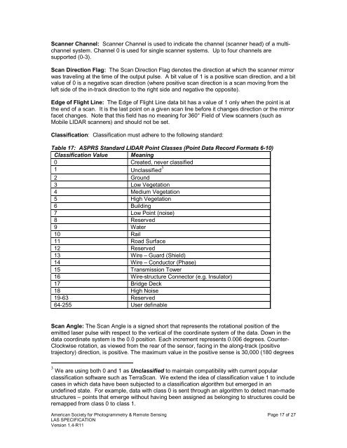
Classification: Classification must adhere to the following standard:<br />
Table 17: ASPRS Standard LIDAR Point Classes (Point Data Record Formats 6-10)<br />
Classification Value Meaning<br />
0 Created, never classified<br />
1 Unclassified 3<br />
2 Ground<br />
3 Low Vegetation<br />
4 Medium Vegetation<br />
5 High Vegetation<br />
6 Building<br />
7 Low Point (noise)<br />
8 Reserved<br />
9 Water<br />
10 Rail<br />
11 Road Surface<br />
12 Reserved<br />
13 Wire <strong>–</strong> Guard (Shield)<br />
14 Wire <strong>–</strong> Conductor (Phase)<br />
15 Transmission Tower<br />
16 Wire-structure Connector (e.g. Insulator)<br />
17 Bridge Deck<br />
18 High Noise<br />
19-63 Reserved<br />
64-255 User definable<br />
Scan Angle: The Scan Angle is a signed short that represents the rotational position of the<br />
emitted laser pulse with respect to the vertical of the coordinate system of the data. Down in the<br />
data coordinate system is the 0.0 position. Each increment represents 0.006 degrees. Counter-<br />
Clockwise rotation, as viewed from the rear of the sensor, facing in the along-track (positive<br />
trajectory) direction, is positive. The maximum value in the positive sense is 30,000 (180 degrees<br />
3 We are using both 0 and 1 as Unclassified to maintain compatibility with current popular<br />
classification software such as TerraScan. We extend the idea of classification value 1 to include<br />
cases in which data have been subjected to a classification algorithm but emerged in an<br />
undefined state. For example, data with class 0 is sent through an algorithm to detect man-made<br />
structures <strong>–</strong> points that emerge without having been assigned as belonging to structures could be<br />
remapped from class 0 to class 1.<br />
American Society for Photogrammetry & Remote Sensing Page 17 of 27<br />
<strong>LAS</strong> <strong>SPECIFICATION</strong><br />
Version <strong>1.4</strong>-<strong>R11</strong>