Operating Instructions And Parts Manual 8-inch Jointer
Operating Instructions And Parts Manual 8-inch Jointer
Operating Instructions And Parts Manual 8-inch Jointer

You also want an ePaper? Increase the reach of your titles
YUMPU automatically turns print PDFs into web optimized ePapers that Google loves.
If the jointer is to be hard-wired to a panel, make<br />
sure a disconnect is available for the operator.<br />
During hard-wiring of the machine, make sure<br />
the fuses have been removed or the breakers<br />
have been tripped in the circuit to which the<br />
jointer will be connected. Place a warning<br />
placard on the fuse holder or circuit breaker to<br />
prevent it being turned on while the machine is<br />
being wired.<br />
Grounding <strong>Instructions</strong><br />
This machine must be grounded. In the event of<br />
a malfunction or breakdown, grounding provides<br />
a path of least resistance for electric current to<br />
reduce the risk of electric shock.<br />
Improper connection of the equipmentgrounding<br />
conductor can result in a risk of<br />
electric shock. The conductor with insulation<br />
having an outer surface that is green with or<br />
without yellow stripes, is the equipmentgrounding<br />
conductor. If repair or replacement of<br />
the electric cord or plug is necessary, do not<br />
connect the equipment-grounding conductor to a<br />
live terminal.<br />
Check with a qualified electrician or service<br />
personnel if the grounding instructions are not<br />
completely understood, or if in doubt as to<br />
whether the tool is properly grounded. Repair or<br />
replace a damaged or worn cord immediately.<br />
IMPORTANT: Make sure the electrical<br />
characteristics listed on the motor nameplate<br />
match those of the power source, and make<br />
sure the circuit on which the jointer will be used<br />
is properly fused and that the wire size is<br />
correct.<br />
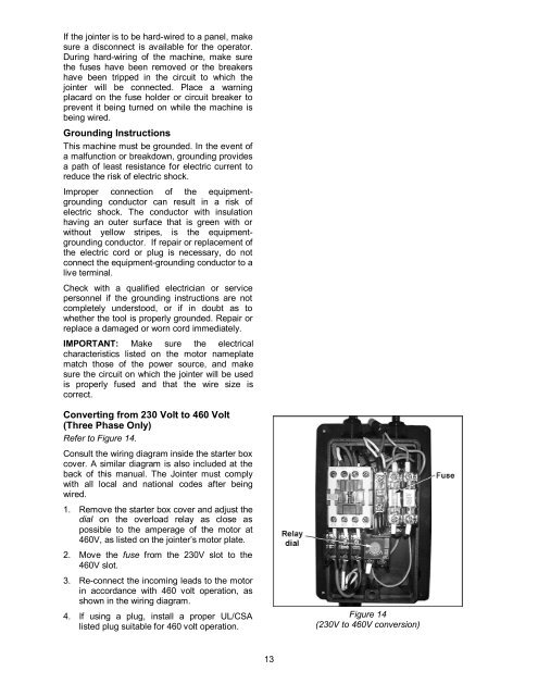
Converting from 230 Volt to 460 Volt<br />
(Three Phase Only)<br />
Refer to Figure 14.<br />
Consult the wiring diagram inside the starter box<br />
cover. A similar diagram is also included at the<br />
back of this manual. The <strong>Jointer</strong> must comply<br />
with all local and national codes after being<br />
wired.<br />
1. Remove the starter box cover and adjust the<br />
dial on the overload relay as close as<br />
possible to the amperage of the motor at<br />
460V, as listed on the jointer’s motor plate.<br />
2. Move the fuse from the 230V slot to the<br />
460V slot.<br />
3. Re-connect the incoming leads to the motor<br />
in accordance with 460 volt operation, as<br />
shown in the wiring diagram.<br />
4. If using a plug, install a proper UL/CSA<br />
listed plug suitable for 460 volt operation.<br />
13<br />
Figure 14<br />
(230V to 460V conversion)