Operating Instructions And Parts Manual 8-inch Jointer
Operating Instructions And Parts Manual 8-inch Jointer
Operating Instructions And Parts Manual 8-inch Jointer

Create successful ePaper yourself
Turn your PDF publications into a flip-book with our unique Google optimized e-Paper software.
Assembly<br />
Exposed metal surfaces, such as the table and<br />
fence, have been given a protective coating at<br />
the factory. This coating should be removed with<br />
a soft cloth and solvent (such as mineral spirits)<br />
once the machine has been assembled. Do not<br />
use an abrasive pad as it may scratch the<br />
exposed surfaces.<br />
NOTE: If any procedure described herein needs<br />
further clarification, consult the assembly<br />
drawings at the back of this manual.<br />
Tools required for assembly:<br />
3mm and 6mm hex (Allen) wrenches<br />
17mm, 14mm, (two)12mm open-end wrenches<br />
screwdriver<br />
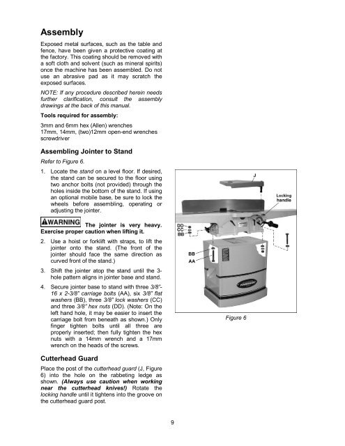
Assembling <strong>Jointer</strong> to Stand<br />
Refer to Figure 6.<br />
1. Locate the stand on a level floor. If desired,<br />
the stand can be secured to the floor using<br />
two anchor bolts (not provided) through the<br />
holes inside the bottom of the stand. If using<br />
an optional mobile base, be sure to lock the<br />
wheels before assembling, operating or<br />
adjusting the jointer.<br />
The jointer is very heavy.<br />
Exercise proper caution when lifting it.<br />
2. Use a hoist or forklift with straps, to lift the<br />
jointer onto the stand. (The front of the<br />
jointer should face the same direction as<br />
curved front of the stand.)<br />
3. Shift the jointer atop the stand until the 3hole<br />
pattern aligns in jointer base and stand.<br />
4. Secure jointer base to stand with three 3/8”-<br />
16 x 2-3/8” carriage bolts (AA), six 3/8” flat<br />
washers (BB), three 3/8” lock washers (CC)<br />
and three 3/8” hex nuts (DD). (Note: On the<br />
left hand hole, it may be easier to insert the<br />
carriage bolt from beneath as shown.) Only<br />
finger tighten bolts until all three are<br />
properly inserted; then fully tighten the hex<br />
nuts with a 14mm wrench and a 17mm<br />
wrench on the heads of the screws.<br />
Cutterhead Guard<br />
Place the post of the cutterhead guard (J, Figure<br />
6) into the hole on the rabbeting ledge as<br />
shown. (Always use caution when working<br />
near the cutterhead knives!) Rotate the<br />
locking handle until it tightens into the groove on<br />
the cutterhead guard post.<br />
9<br />
Figure 6