Max Planck Institute for Astronomy - Annual Report 2007
Max Planck Institute for Astronomy - Annual Report 2007
Max Planck Institute for Astronomy - Annual Report 2007

Create successful ePaper yourself
Turn your PDF publications into a flip-book with our unique Google optimized e-Paper software.
94 IV. Instrumental Developments and Projects<br />
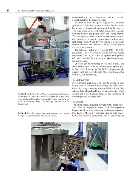
Fig. IV.1.3: Lucifer in the MPIA’s experimentation hall during<br />
the integration phase: The upper crystal portion is just being<br />
removed, the cold structure surrounded by super-insulation foil<br />
inside is becoming visible. The telescope simulator is in the<br />
background.<br />
Fig. IV.1.4: The cable routing in the cryostat can be freely seen<br />
through the open flange <strong>for</strong> the cable bushings.<br />
transmitted to the wave front sensor and serves as the<br />
control signal <strong>for</strong> the adaptive optics.<br />
In order to limit the space required by the entire<br />
system, the triple lens collimator which follows in the<br />
beam path is pleated with the help of three flat mirrors.<br />
The pupil plane in the collimated beam path coincides<br />
with the plane of the grating (or of the folding mirror).<br />
The subsequent camera systems are housed on a wheel,<br />
thus making it possible to choose between three different<br />
image scales. While the f/30 camera is a cassegrain<br />
system with dual lens corrector, the two faster cameras<br />
are pure lens systems.<br />
The detector is a Hawaii-II type with 2048 2048 18-<br />
µm pixels. The focus position can be corrected during<br />
operations. The 1.8, 3.75, and 30 aperture ratio provide<br />
0.25, 0.12, and 0.015 arc seconds per pixel imaging scales,<br />
respectively.<br />
28 filters can be positioned on two filter wheels. The<br />
filter wheels are located on the convergent optical path<br />
in front of the detector (see Fig. IV.1.2). At present eight<br />
narrow band and ten wide band filters are designed <strong>for</strong><br />
both Lucifer instruments.<br />
The Calibration Unit<br />
For calibration purposes, a unit can be swung in front<br />
of the cryostat window which images the light from a<br />
calibration lamp emanating from an Ulbricht integrating<br />
sphere. Both a broadband lamp <strong>for</strong> the calibration of the<br />
camera and a gas discharge lamp <strong>for</strong> the calibration of<br />
wavelengths are available here.<br />
The Cryostat<br />
The entire optics, including the telescope’s focal plane,<br />
are cooled in a cryostat to around 70 K. The cryostat’s<br />
housing is a lightweight stainless steel construction (see<br />
Fig. IV.1.3). All supply openings such as plug flange,<br />
CCC cooler, vacuum connections, and in- and outflow of