Max Planck Institute for Astronomy - Annual Report 2007
Max Planck Institute for Astronomy - Annual Report 2007
Max Planck Institute for Astronomy - Annual Report 2007

Create successful ePaper yourself
Turn your PDF publications into a flip-book with our unique Google optimized e-Paper software.
96 IV. Instrumental Developments and Projects<br />
• Two gratings and a plane mirror are housed on the<br />
grating exchange unit. The drive serves on the one<br />
hand to change the grating or <strong>for</strong> the switch between<br />
the camera mode and spectroscopy and, on the other<br />
hand, to tune the central wavelength<br />
• The two filter wheels provide room <strong>for</strong> 28 filters.<br />
Currently 18 positions are occupied with filters. In<br />
each wheel, an additional position is reserved <strong>for</strong> the<br />
differential camera.<br />
• In front of the camera wheel an additional lens can be<br />
swiveled in to take an image of the pupil on the detector<br />
with an f/1.8 camera. In this manner the alignment<br />
of telescope and instrument can be controlled.<br />
• The camera revolver houses the three f/1.8, f/3.75,<br />
and f/30 camera systems. All three can be used both<br />
as an imager and as a spectrograph. The f/30 camera<br />
can also be used as a differential methane band camera<br />
while the f/1.8 also serves with a <strong>for</strong>e-lens to take<br />
images of the pupil.<br />
• By correcting the focusing by up to 5 mm, differences<br />
in the optic filter thickness can be offset.<br />
The Mask Exchange Mechanism<br />
Multi-object spectroscopy will likely be the most used<br />
mode on Lucifer. Both Lucifer devices are equipped<br />
with exchange loaders <strong>for</strong> the slit masks. Ten long-slit<br />
and field masks are available as standard equipment. In<br />
addition, 23 multi-slit masks (Mos masks) can be ex-<br />
Fig. IV.1.6: Fan-out board and detector array in the test cryostat<br />
during the first test of the detector.<br />
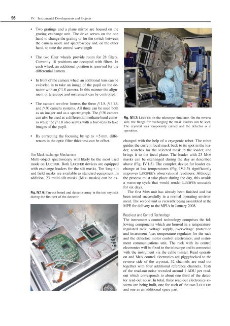
Fig. IV.1.7: Lucifer on the telescope simulator. On the reverse<br />
side, the flange <strong>for</strong> exchanging the mask loaders can be seen.<br />
The cryostat was temporarily cabled and the detector is in<br />
operation.<br />
changed with the help of a cryogenic robot. The robot<br />
guides the current focal mask back to its spot in the loader,<br />
searches <strong>for</strong> the selected mask in the loader, and<br />
brings it to the focal plane. The loader with 23 Mos<br />
masks can be exchanged during the day as described<br />
above (Fig. IV.1.5). The complex device <strong>for</strong> loader exchange<br />
at low temperatures (Fig. IV.1.5) significantly<br />
improves Lucifer’s observational readiness: Although<br />
the process must take place during the day, this avoids<br />
a warm-up cycle that would render Lucifer unusable<br />
<strong>for</strong> six days.<br />
The first Mos unit has already been finished and has<br />
been tested successfully in a normal operating environment.<br />
The second unit is currently being assembled at the<br />
MPE <strong>for</strong> delivery to the MPIA in January 2008.<br />
Read-out and Control Technology<br />
The instrument’s control technology comprises the following<br />
components which are housed in a temperatureregulated<br />
rack: voltage supply, overvoltage protection<br />
and instrument fuse; temperature regulator <strong>for</strong> the rack<br />
and the detector; motor control electronics; and instrument<br />
communications unit. The rack with its control<br />
electronics will be fixed to the telescope and is connected<br />
with the instrument via the cable twister. Read operation<br />
and Mos control electronics are piggybacked to the<br />
reverse side of the cryostat. 32 channels are read out<br />
together with four additional reference channels. Tests<br />
of the read-out noise revealed around 1 ADU per readout<br />
which corresponds to about one third of the detector<br />
read-out noise. In total, three read-out electronics systems<br />
are being built, one <strong>for</strong> each of the two Lucifers<br />
and one as an additional spare part.