Download - NASA
Download - NASA
Download - NASA
Create successful ePaper yourself
Turn your PDF publications into a flip-book with our unique Google optimized e-Paper software.
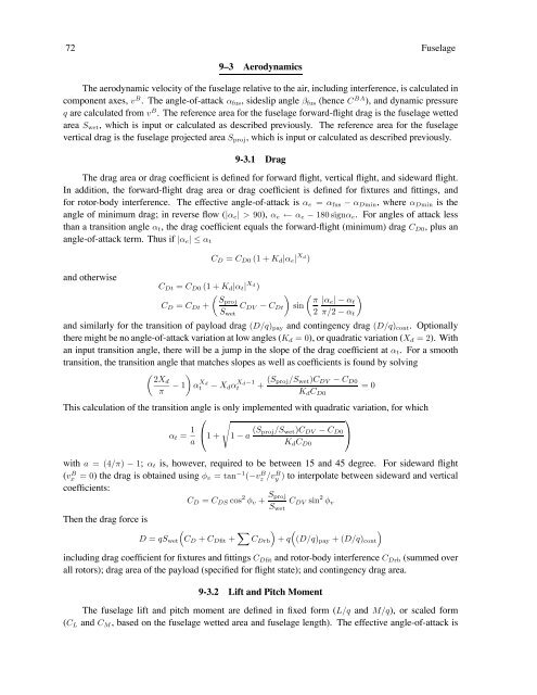
72 Fuselage<br />
9–3 Aerodynamics<br />
The aerodynamic velocity of the fuselage relative to the air, including interference, is calculated in<br />
component axes, v B . The angle-of-attack αfus, sideslip angle βfus (hence C BA ), and dynamic pressure<br />
q are calculated from v B . The reference area for the fuselage forward-flight drag is the fuselage wetted<br />
area Swet, which is input or calculated as described previously. The reference area for the fuselage<br />
vertical drag is the fuselage projected area Sproj, which is input or calculated as described previously.<br />
9-3.1 Drag<br />
The drag area or drag coefficient is defined for forward flight, vertical flight, and sideward flight.<br />
In addition, the forward-flight drag area or drag coefficient is defined for fixtures and fittings, and<br />
for rotor-body interference. The effective angle-of-attack is αe = αfus − αDmin, where αDmin is the<br />
angle of minimum drag; in reverse flow (|αe| > 90), αe ← αe − 180 signαe. For angles of attack less<br />
than a transition angle αt, the drag coefficient equals the forward-flight (minimum) drag CD0, plus an<br />
angle-of-attack term. Thus if |αe| ≤αt<br />
and otherwise<br />
CDt = CD0 (1 + Kd|αt| Xd )<br />
CD = CDt +<br />
CD = CD0 (1 + Kd|αe| Xd )<br />
<br />
Sproj<br />
CDV − CDt<br />
Swet<br />
<br />
<br />
π<br />
sin<br />
2<br />
<br />
|αe|−αt<br />
π/2 − αt<br />
and similarly for the transition of payload drag (D/q)pay and contingency drag (D/q)cont. Optionally<br />
there might be no angle-of-attack variation at low angles (Kd =0), or quadratic variation (Xd =2). With<br />
an input transition angle, there will be a jump in the slope of the drag coefficient at αt. For a smooth<br />
transition, the transition angle that matches slopes as well as coefficients is found by solving<br />
<br />
2Xd<br />
− 1 α<br />
π Xd<br />
t − Xdα Xd−1<br />
t + (Sproj/Swet)CDV − CD0<br />
=0<br />
KdCD0<br />
This calculation of the transition angle is only implemented with quadratic variation, for which<br />
αt = 1<br />
⎛ <br />
⎝1+<br />
a<br />
1 − a (Sproj/Swet)CDV<br />
⎞<br />
− CD0 ⎠<br />
KdCD0<br />
with a =(4/π) − 1; αt is, however, required to be between 15 and 45 degree. For sideward flight<br />
(v B x =0) the drag is obtained using φv = tan −1 (−v B z /v B y ) to interpolate between sideward and vertical<br />
coefficients:<br />
CD = CDS cos 2 φv + Sproj<br />
CDV sin<br />
Swet<br />
2 φv<br />
Then the drag force is<br />
<br />
D = qSwet CD + CDfit + <br />
<br />
CDrb + q (D/q)pay +(D/q)cont<br />
including drag coefficient for fixtures and fittings CDfit and rotor-body interference CDrb (summed over<br />
all rotors); drag area of the payload (specified for flight state); and contingency drag area.<br />
9-3.2 Lift and Pitch Moment<br />
The fuselage lift and pitch moment are defined in fixed form (L/q and M/q), or scaled form<br />
(CL and CM, based on the fuselage wetted area and fuselage length). The effective angle-of-attack is


