Download - NASA
Download - NASA
Download - NASA
You also want an ePaper? Increase the reach of your titles
YUMPU automatically turns print PDFs into web optimized ePapers that Google loves.
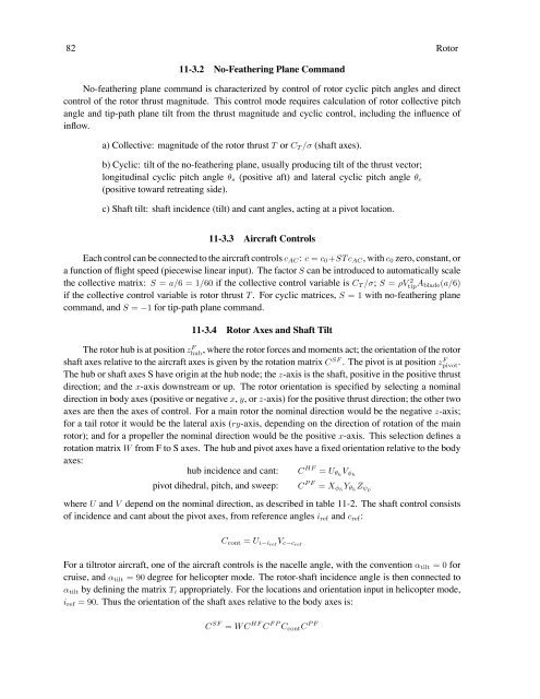
82 Rotor<br />
11-3.2 No-Feathering Plane Command<br />
No-feathering plane command is characterized by control of rotor cyclic pitch angles and direct<br />
control of the rotor thrust magnitude. This control mode requires calculation of rotor collective pitch<br />
angle and tip-path plane tilt from the thrust magnitude and cyclic control, including the influence of<br />
inflow.<br />
a) Collective: magnitude of the rotor thrust T or CT /σ (shaft axes).<br />
b) Cyclic: tilt of the no-feathering plane, usually producing tilt of the thrust vector;<br />
longitudinal cyclic pitch angle θs (positive aft) and lateral cyclic pitch angle θc<br />
(positive toward retreating side).<br />
c) Shaft tilt: shaft incidence (tilt) and cant angles, acting at a pivot location.<br />
11-3.3 Aircraft Controls<br />
Each control can be connected to the aircraft controls cAC: c = c0+STcAC, with c0 zero, constant, or<br />
a function of flight speed (piecewise linear input). The factor S can be introduced to automatically scale<br />
the collective matrix: S = a/6 =1/60 if the collective control variable is CT /σ; S = ρV 2<br />
tip Ablade(a/6)<br />
if the collective control variable is rotor thrust T . For cyclic matrices, S =1with no-feathering plane<br />
command, and S = −1 for tip-path plane command.<br />
11-3.4 Rotor Axes and Shaft Tilt<br />
The rotor hub is at position zF hub , where the rotor forces and moments act; the orientation of the rotor<br />
shaft axes relative to the aircraft axes is given by the rotation matrix CSF . The pivot is at position zF pivot.<br />
The hub or shaft axes S have origin at the hub node; the z-axis is the shaft, positive in the positive thrust<br />
direction; and the x-axis downstream or up. The rotor orientation is specified by selecting a nominal<br />
direction in body axes (positive or negative x, y,orz-axis) for the positive thrust direction; the other two<br />
axes are then the axes of control. For a main rotor the nominal direction would be the negative z-axis;<br />
for a tail rotor it would be the lateral axis (ry-axis, depending on the direction of rotation of the main<br />
rotor); and for a propeller the nominal direction would be the positive x-axis. This selection defines a<br />
rotation matrix W from F to S axes. The hub and pivot axes have a fixed orientation relative to the body<br />
axes:<br />
hub incidence and cant: C HF = UθhVφh pivot dihedral, pitch, and sweep: C PF = XφhYθh Zψp<br />
where U and V depend on the nominal direction, as described in table 11-2. The shaft control consists<br />
of incidence and cant about the pivot axes, from reference angles iref and cref:<br />
Ccont = Ui−iref Vc−cref<br />
For a tiltrotor aircraft, one of the aircraft controls is the nacelle angle, with the convention αtilt =0for<br />
cruise, and αtilt =90degree for helicopter mode. The rotor-shaft incidence angle is then connected to<br />
αtilt by defining the matrix Ti appropriately. For the locations and orientation input in helicopter mode,<br />
iref =90. Thus the orientation of the shaft axes relative to the body axes is:<br />
C SF = WC HF C FP CcontC PF


