ATAC i system - Energimyndigheten
ATAC i system - Energimyndigheten
ATAC i system - Energimyndigheten

You also want an ePaper? Increase the reach of your titles
YUMPU automatically turns print PDFs into web optimized ePapers that Google loves.
3<br />
candidate, the measurement strategy is evaluated in detail and a final strategy will be decided<br />
as soon as possible. The preliminary plan is to build the unit in the laboratory of the<br />
department and that it will be built by a company with previous experience from construction<br />
of similar units. A preliminary design has been developed and discussed with that company.<br />
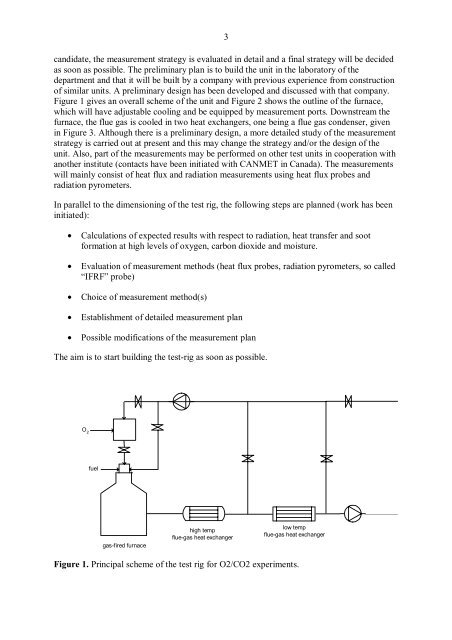
Figure 1 gives an overall scheme of the unit and Figure 2 shows the outline of the furnace,<br />
which will have adjustable cooling and be equipped by measurement ports. Downstream the<br />
furnace, the flue gas is cooled in two heat exchangers, one being a flue gas condenser, given<br />
in Figure 3. Although there is a preliminary design, a more detailed study of the measurement<br />
strategy is carried out at present and this may change the strategy and/or the design of the<br />
unit. Also, part of the measurements may be performed on other test units in cooperation with<br />
another institute (contacts have been initiated with CANMET in Canada). The measurements<br />
will mainly consist of heat flux and radiation measurements using heat flux probes and<br />
radiation pyrometers.<br />
In parallel to the dimensioning of the test rig, the following steps are planned (work has been<br />
initiated):<br />
• Calculations of expected results with respect to radiation, heat transfer and soot<br />
formation at high levels of oxygen, carbon dioxide and moisture.<br />
• Evaluation of measurement methods (heat flux probes, radiation pyrometers, so called<br />
“IFRF” probe)<br />
• Choice of measurement method(s)<br />
• Establishment of detailed measurement plan<br />
• Possible modifications of the measurement plan<br />
The aim is to start building the test-rig as soon as possible.<br />
O 2<br />
fuel<br />
gas-fired furnace<br />
high temp<br />
flue-gas heat exchanger<br />
low temp<br />
flue-gas heat exchanger<br />
Figure 1. Principal scheme of the test rig for O2/CO2 experiments.