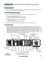
G3 Series PROFIBUS-DP Technical Manual - ASCO Numatics
G3 Series PROFIBUS-DP Technical Manual - ASCO Numatics
G3 Series PROFIBUS-DP Technical Manual - ASCO Numatics
You also want an ePaper? Increase the reach of your titles
YUMPU automatically turns print PDFs into web optimized ePapers that Google loves.
Diagnostics<br />
Communication Module LED Functions<br />
<strong>G3</strong> <strong>Series</strong> <strong>PROFIBUS</strong>‐<strong>DP</strong> <strong>Technical</strong><br />
<strong>Manual</strong><br />
Upon power up, the Module and Network Status LEDs indicate the state of the unit. There are two LEDs on<br />
the <strong>G3</strong> <strong>PROFIBUS</strong>-<strong>DP</strong> node. The LEDs functions are described in the table below.<br />
LED Name Color Status Description<br />
Red ON<br />
Bus Error. Bus connection failed or off-line; Invalid<br />
parameterization, configuration, or bus address.”<br />
Normal operation. The bus link is OK. Baud rate, detected<br />
NETWORK<br />
Green ON parameterization and configuration OK. Unit is in data exchange<br />
STATUS<br />
mode.<br />
The module configuration (I/O and valves) in the user<br />
Green Red FLASHING application is different than the physical configuration of the<br />
manifold.<br />
MODULE<br />
STATUS<br />
Red<br />
Green<br />
Green Red<br />
ON<br />
ON<br />
FLASHING<br />
Critical hardware fault. The microprocessor is not running.<br />
Normal operation. Node hardware is OK.<br />
Module is in self-test mode. Cycle power to end self-test mode.<br />
TD<strong>G3</strong>PTTM1-2EN 02/09<br />
Subject to change without notice<br />
www.numatics.com/g3<br />
Page 17<br />
Supprimé : DeviceNet


