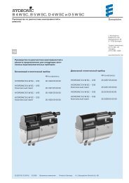
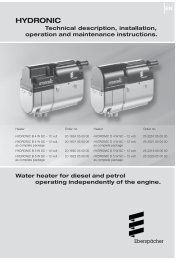
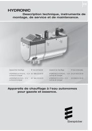
Hydronic M-II (Water Heater) - Espar
Hydronic M-II (Water Heater) - Espar
Hydronic M-II (Water Heater) - Espar

You also want an ePaper? Increase the reach of your titles
YUMPU automatically turns print PDFs into web optimized ePapers that Google loves.
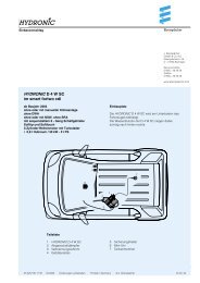
Installation Procedures<br />
<strong>Heater</strong> Plumbing<br />
The heater is incorporated into the engineʼs cooling system for<br />
engine preheating.<br />
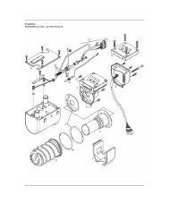
Engine Plumbing<br />
Follow these guidelines and refer to the engine plumbing diagram<br />
shown below.<br />
• Install hose fittings into the engine block for pick-up and return<br />
lines.<br />
• Use existing holes in the engine block (ie. remove<br />
blanking plugs when possible).<br />
• Use shut off valves to ensure the system can be isolated from<br />
the engine when not in use. Alternatively “T” piece connectors<br />
in existing coolant hoses can be used if no blanking plugs are<br />
available.<br />
• Provide 20mm (3/4” ) hose barbs for hose connections.<br />
• Use 20mm (3/4” ) hoses to ensure adequate coolant flow.<br />
• Keep the pick up and return points as far apart as possible to<br />
ensure good heat distribution.<br />
10<br />
<strong>Water</strong> out<br />
<strong>Water</strong> in<br />
• Take the coolant from a low point on the engine to reduce<br />
aeration in the system.<br />
• Ensure proper direction of coolant flow by taking coolant from a<br />
high pressure point in the engine and returning it to a low pressure<br />
point. (ie. pickup from back of block and return to the<br />
suction side of the engine's water pump).<br />
• Ensure adequate flow rate through the heater by comparing the<br />
incoming and outgoing coolant temperatures while the heater is<br />
running. If the rise in temperature exceeds 10°C (18°F), coolant<br />
flow must be increased by modifying the plumbing.<br />
• Ensure the heater and water pump are installed as low as possible<br />
to allow the purging of air.<br />
• If a bunk heat exchanger is incorporated into the system,<br />
proper plumbing layouts must be followed.<br />
4 2<br />
Caution: It is possible for the coolant and components of the<br />
coolant circuit to get very hot.<br />
• Parts conveying water must be routed and fastened in such<br />
a way that they pose no temperature risk to man, animals or<br />
material sensitive to temperature from radiation / direct<br />
contact.<br />
• Before working on the coolant circuit, switch the heater off<br />
and wait until all components have cooled down completely,<br />
if necessary where safety gloves.<br />
Caution:<br />
• When installing the heater, please take note of the direction<br />
of flow of the coolant circuit.<br />
• Fill the heater and water hoses with coolant before connecting<br />
to the coolant circuit.<br />
• Route the water hoses without any kinks, and in a rising<br />
position if possible.<br />
• When routing the water pipes, observe a sufficient clearance<br />
to hot vehicle parts.<br />
• Protect all water hoses / water pipes from chafing and from<br />
extreme temperatures.<br />
• Secure all hose connections with hose clips.<br />
• After the vehicle has been operating for 2 hours or travelled<br />
100 km, tighten the hose clips again.<br />
• The minimum water flow rate is only guaranteed if the temperature<br />
difference of the heating medium does not exceed<br />
15°C (60°C) between water inlet and water outlet during<br />
heating.<br />
• Only overpressure valves with an opening pressure of min.<br />
6 psi – max. 30 psi bar may be used in the coolant circuit.<br />
• The coolant liquid must contain at least 10 % antifreeze all<br />
year round as corrosion protection.<br />
• The cooling liquid must contain sufficient antifreeze for low<br />
temperatures.<br />
• Before commissioning the heater or after changing the<br />
cooling liquid, the whole coolant circuit including heater must<br />
be vented free of bubbles according to the instructions issued<br />
by the vehicle manufacturer.<br />
• Only top up with coolant approved by the vehicle manufacturer.<br />
1<br />
3<br />
1 <strong>Heater</strong><br />
2 Non-return valve (Optional)<br />
3 Heat exchanger<br />
4 Vehicle engine