Hydronic M-II (Water Heater) - Espar
Hydronic M-II (Water Heater) - Espar
Hydronic M-II (Water Heater) - Espar

Create successful ePaper yourself
Turn your PDF publications into a flip-book with our unique Google optimized e-Paper software.
*<br />
<strong>Hydronic</strong> M-<strong>II</strong> (<strong>Water</strong> <strong>Heater</strong>)<br />
<br />
<br />
<br />
<br />
<br />
<br />
<br />
<br />
<br />
<br />
www.espar.com <br />
<br />
<br />
.<br />
<br />
<br />
<br />
<br />
<br />
<br />
<strong>Espar</strong> <strong>Heater</strong> Systems
Table of Contents Page<br />
Introduction <strong>Heater</strong> Warnings .............................................. 3<br />
Technical Data <strong>Hydronic</strong> M8 Biodiesel .............................................. 4<br />
Technical Data <strong>Hydronic</strong> M10 ............................................. 5<br />
Technical Data <strong>Hydronic</strong> M12 .............................................. 6<br />
<strong>Heater</strong> Components .............................................. 7<br />
Principal Dimensions .............................................. 8<br />
Installation Procedures <strong>Heater</strong> Location / Mounting/ Fastening .............................................. 9<br />
<strong>Heater</strong> & Engine Plumbing .............................................. 10<br />
Fuel Quality .............................................. 11<br />
Fuel System .............................................. 12<br />
Electrical Connections .............................................. 14<br />
Exhaust / Intake Connections .............................................. 15<br />
Operating Switches: 7 Day Timer .............................................. 16<br />
Push/Pull Switch, Programmable Timer .............................................. 18<br />
<strong>Heater</strong> Operation Pre-Start Procedures / Start-Up .............................................. 20<br />
Heating Mode / Termperature Drop .............................................. 20<br />
Switching Off /Safety Equipment .............................................. 20<br />
<strong>Heater</strong> Wiring .............................................. 21<br />
Parts List for Wiring Diagram .............................................. 22<br />
<strong>Heater</strong> Wiring Diagram .............................................. 23<br />
Controler wireing diagrams .............................................. 24<br />
Maintenance, Periodic Maintenance .............................................. 25<br />
Troubleshooting & Basic Troubleshooting / Self Diagnostics .............................................. 25<br />
Repairs Fault codes / Description / Repair .............................................. 26<br />
Repair Instructions .............................................. 30<br />
Repair Steps .............................................. 31<br />
Fuel Quantity .............................................. 47<br />
<strong>Heater</strong> Components Parts Diagram .............................................. 48<br />
Description & Part #ʼs .............................................. 49<br />
Parts Diagram - Boxed units .............................................. 50<br />
Description & Part #ʼs .............................................. 51<br />
Special Notes<br />
Note: Highlight areas requiring special attention or clarification.<br />
Caution: Indicates that personal injury or damage to equipment may occur unless specific guidelines are followed.<br />
Warning: Indicates that serious or fatal injury may result if specific guidelines are not followed.<br />
This publication was correct at the time of going to print. However, <strong>Espar</strong> Inc. has a policy of continuous improvement<br />
and reserves the right to amend any specifications without prior notice.
Introduction
Introduction<br />
4<br />
Technical data<br />
<strong>Heater</strong> type HYDRONIC M-<strong>II</strong><br />
<strong>Heater</strong> HYDRONIC M8 Biodiesel<br />
Version D 8 W<br />
Heating<br />
medium<br />
Control<br />
of<br />
the<br />
heat<br />
flow<br />
Heat flow (BTU) (Watt)<br />
Figures for operation with diesel fuel. If operated with Biodiesel<br />
the heat flow can reduce by up to 15 %.<br />
Fuel<br />
consumption<br />
( g/<br />
h)<br />
(l/h)<br />
Power<br />
<strong>Water</strong>,<br />
Cooling<br />
fluid<br />
High<br />
Medium<br />
Low<br />
BTU 27297 17061 11943 5118<br />
Watt 8000 5000 3500 1500<br />
g/h<br />
l/h<br />
Electrical power (Watt) in operation 55 46 39 35<br />
Rated<br />
voltage<br />
at<br />
start<br />
– after<br />
25<br />
Sec.<br />
Stand by<br />
Operating range<br />
• Lower voltage limit: An undervoltage protection in<br />
the controller switches the heater off on reaching the<br />
voltage limit.<br />
• Upper voltage limit: An overvoltage protection in the<br />
controller switches the heater off on reaching the<br />
voltage limit.<br />
Tolerable<br />
Flo<br />
w rate<br />
operating<br />
pressure<br />
of<br />
the<br />
Minimum<br />
water<br />
flo<br />
water<br />
pump<br />
at<br />
2 psi<br />
w rate<br />
of<br />
the<br />
Tolerable<br />
operating<br />
temperature<br />
heater<br />
Weight with controller and water pump,<br />
without dosing pump<br />
<strong>Heater</strong> / Control box Diesel<br />
Biodiesel<br />
Dosing pump<br />
Biodiesel<br />
Diesel<br />
Caution:<br />
Failure to comply with the technical data can<br />
result in malfunctions.<br />
0.24<br />
0.90<br />
12<br />
Volt<br />
10<br />
Volt<br />
15<br />
Volt<br />
Operation<br />
0.17<br />
0.65<br />
200<br />
32<br />
0.11<br />
0.40<br />
up to 200 kPa - 30 psi<br />
1400 l/h<br />
500 l/h<br />
370 g/h<br />
132 g/h<br />
Not<br />
approx. 6.2 kg - 13.7 lb<br />
24<br />
Volt<br />
20<br />
Volt<br />
30<br />
Volt<br />
running<br />
0.05<br />
0.18<br />
– 40 °F to +176 °F / –40 °C to +80 °C –40 °F to +185 °F / –40 °C to +85 °C<br />
+17.6 °F to +176 °F / –8 °C to +80 °C –40 °F to +185 °F / –40 °C to +85 °C<br />
– 40 °F to +122 °F / –40 °C to +50 °C –40 °F to +185 °F / –40 °C to +85 °C<br />
+17.6 °F to +122 °F / –8 °C to +50 °C –40 °F to +185 °F / –40 °C to +85 °C
Introduction<br />
Technical data<br />
<strong>Heater</strong> type HYDRONIC M-<strong>II</strong><br />
<strong>Heater</strong> HYDRONIC M10<br />
Version D 10 W<br />
Heating<br />
medium<br />
Control<br />
of<br />
the<br />
heat<br />
flow<br />
Heat<br />
flow<br />
Fuel<br />
consumption<br />
Electrical power (Watt)<br />
Rated<br />
voltage<br />
at<br />
<strong>Water</strong>,<br />
Cooling<br />
fluid<br />
BTU 32415 27297 11943 5118<br />
Watt 9500 8000 3500 1500<br />
(g/h)<br />
(l/h)<br />
start<br />
– after<br />
25<br />
Sec.<br />
Operating range<br />
• Lower voltage limit: An undervoltage protection in<br />
the controller switches the heater off on reaching the<br />
voltage limit.<br />
• Upper voltage limit: An overvoltage protection in the<br />
controller switches the heater off on reaching the<br />
voltage limit.<br />
Tolerable<br />
operating<br />
pressure<br />
Flo<br />
w rate<br />
of<br />
the<br />
Minimum<br />
water<br />
flo<br />
water<br />
pump<br />
at<br />
2 psi<br />
w rate<br />
of<br />
the<br />
Tolerable<br />
operating<br />
temperature<br />
heater<br />
Weight with controller and water pump,<br />
without dosing pump<br />
<strong>Heater</strong> / Control box<br />
Dosing pump<br />
Caution:<br />
Failure to comply with the technical data can<br />
result in malfunctions.<br />
Power<br />
0.32<br />
1.2<br />
12<br />
Volt<br />
10<br />
Volt<br />
15<br />
Volt<br />
Operation<br />
High<br />
0.24<br />
0.9<br />
120<br />
32<br />
Medium<br />
0.11<br />
0.4<br />
up to 200 kPa - 30 psi<br />
1400 l/h - 370 g/h<br />
500 l/h - 132 g/h<br />
Not<br />
approx. 6.2 g/h - 13.7 lb<br />
24<br />
Volt<br />
20<br />
Volt<br />
30<br />
Volt<br />
running<br />
0.05<br />
0.18<br />
in operation 86 60 39 35<br />
Stand by<br />
Low<br />
–40 °F to +176 °F / –40 °C to +80 °C –40 °F to +185 °F / –40 °C to +85 °C<br />
–40 °F to +122 °F / –40 °C to +50 °C –40 °F to +185 °F / –40 °C to +85 °C<br />
5
Introduction<br />
6<br />
Technical data<br />
<strong>Heater</strong> type HYDRONIC M-<strong>II</strong><br />
<strong>Heater</strong> HYDRONIC M12<br />
Version D 12 W<br />
Heating<br />
medium<br />
Control<br />
of<br />
the<br />
heat<br />
flow<br />
Heat<br />
flow<br />
Fuel<br />
consumption<br />
Electrical power (Watt)<br />
Rated<br />
voltage<br />
at<br />
Power<br />
High<br />
<strong>Water</strong>,<br />
Cooling<br />
fluid<br />
Medium<br />
1 Medium<br />
2 Medium<br />
3<br />
Low<br />
in operation 132 86 46 39 35 34<br />
start<br />
– after<br />
25<br />
Sec.<br />
Operating range<br />
• Lower voltage limit: An undervoltage protection in<br />
the controller switches the heater off on reaching the<br />
voltage limit.<br />
• Upper voltage limit: An overvoltage protection in the<br />
controller switches the heater off on reaching the<br />
voltage limit.<br />
Tolerable<br />
operating<br />
pressure<br />
Flo<br />
w rate<br />
of<br />
the<br />
Minimum<br />
water<br />
flo<br />
water<br />
pump<br />
at<br />
2 psi<br />
w rate<br />
of<br />
the<br />
Tolerable<br />
operating<br />
temperature<br />
heater<br />
Weight with controller and water pump,<br />
without dosing pump<br />
<strong>Heater</strong> / Control box<br />
Caution:<br />
Failure to comply with the technical data can<br />
result in malfunctions.<br />
BTU<br />
(g/h)<br />
(l/h)<br />
Stand by<br />
Dosing pump<br />
42000<br />
.40<br />
1.5<br />
32415<br />
.32<br />
1.2<br />
12<br />
Volt<br />
10<br />
Volt<br />
15<br />
Volt<br />
Operation<br />
17061<br />
.17<br />
0.65<br />
120<br />
32<br />
11943 5118<br />
.11 .05<br />
0.40 0.18<br />
up to 200 kPa - 30 psi<br />
1400 l/h - 370 g/h<br />
500 l/h - 132 g/h<br />
Not<br />
approx. 6.2 g/h - 13.7 lb.<br />
24<br />
Volt<br />
20<br />
Volt<br />
30<br />
Volt<br />
running<br />
4095<br />
.04<br />
0.15<br />
–40 °F to +176 °F / –40 °C to +80 °C –40 °F to +185 °F / –40 °C to +85 °C<br />
–40 °F to +122 °F / –40 °C to +50 °C –40 °F to +185 °F / –40 °C to +85 °C
Introduction<br />
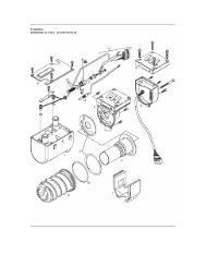
<strong>Heater</strong> Components<br />
1<br />
2 3<br />
WO<br />
1 Control box<br />
2 Burner motor<br />
3 Glow plug<br />
4 Flame pipe<br />
5 Overheating sensor<br />
6 Heat exchanger<br />
7 <strong>Water</strong> pump<br />
8 Combustion chamber<br />
9 Flame sensor<br />
CA<br />
F<br />
E<br />
9 8 7<br />
WI = <strong>Water</strong> inlet<br />
WO = <strong>Water</strong> outlet<br />
CA = Combustion air<br />
F = Fuel<br />
E = Exhaust<br />
4<br />
5<br />
6<br />
WI<br />
7
Introduction<br />
Principal Dimensions<br />
8<br />
CA E<br />
Permissible installation positions<br />
1 <strong>Water</strong> outlet socket, heater<br />
2 <strong>Water</strong> inlet socket, water pump<br />
F WO<br />
M8 (x4)<br />
WI<br />
E Exhaust<br />
F Fuel<br />
CA Combustion air<br />
WO <strong>Water</strong> outlet<br />
WI <strong>Water</strong> inlet<br />
* All measurements in millimeters 25.4 mm = 1”<br />
Boxed <strong>Heater</strong>s Insure:<br />
Minimum installation distance (clearance) to<br />
open the lid and to dismount the glow pin and<br />
the control unit.<br />
Insure:<br />
Minimum installation distance (clearance) to<br />
take in combustion air.
Installation Procedures<br />
Principal Dimensions - Boxed Version<br />
197 mm<br />
(7.76”)<br />
<strong>Heater</strong> Location<br />
Always mount the heater in a protected area. Eg: storage compartment,<br />
engine compartments, step box or battery box.<br />
<strong>Espar</strong> recommends you use the boxed unit. Refer to fig. 1<br />
When mounting the heater adhere to the following conditions:<br />
• Situate the heater below the normal coolant level of the engine.<br />
• Guard against excessive road spray.<br />
• Keep coolant hoses, fuel lines and electrical wiring as short<br />
as possible.<br />
<strong>Heater</strong> Mounting<br />
Mount the heater using the four (4) shock mounts provided<br />
with kit and one of the following mounting methods:<br />
• Use the Side Mount Bracket to mount the heater on the<br />
side of the frame rail.<br />
• Use a spare step box or battery box.<br />
• Use the saddle bracket and hardware provided<br />
Caution: Guard the heater against excessive road spray to<br />
avoid internal corrosion.<br />
Mounting and Fastening<br />
Fix the unit holder from the installation kit to the heater<br />
using 4 hexagon screws M8 and 4 spring washers.<br />
Fix the heater and the mounted unit holder in a suitable<br />
place in the vehicle using 5 hexagon screws M8, 5 spring<br />
washers and 5 hexagon nuts M8<br />
1 <strong>Heater</strong><br />
2 <strong>Heater</strong> bracket<br />
317 mm<br />
(12.4”)<br />
430 mm (16.9”)<br />
Arrangement of the heater<br />
Parts of the structure and other components near the heater<br />
must be protected from excess heat exposure and possible<br />
contamination from fuel or oil.<br />
The heater must not pose a fire hazard even when it<br />
overheats.<br />
– This requirement is deemed to be fulfilled when<br />
adequate clearance to all parts is observed during<br />
installation, sufficient ventilation is provided and fireproof<br />
materials or heat plates are used.<br />
The heater must not be located in the passenger compartment.<br />
A unit may however be used in a hermetically sealed housing<br />
which also corresponds to the conditions stated above.<br />
The factory nameplate or duplicate must be affixed so that it<br />
can still be easily read when the heater is installed in the<br />
vehicle.<br />
All appropriate precautions must be taken when<br />
arranging the heater to minimise the risk of injuries<br />
to persons or damage to other property.<br />
Box Base<br />
P/N 25 2800 40 10 02<br />
Box Lid<br />
P/N 25 2800 40 10 03<br />
Side Mount Bracket<br />
P/N 20 2900 40 00 75<br />
Fig. 1<br />
Intake Silencer<br />
always needed<br />
P/N 25 1786 80 02 00<br />
9
Installation Procedures<br />
<strong>Heater</strong> Plumbing<br />
The heater is incorporated into the engineʼs cooling system for<br />
engine preheating.<br />
Engine Plumbing<br />
Follow these guidelines and refer to the engine plumbing diagram<br />
shown below.<br />
• Install hose fittings into the engine block for pick-up and return<br />
lines.<br />
• Use existing holes in the engine block (ie. remove<br />
blanking plugs when possible).<br />
• Use shut off valves to ensure the system can be isolated from<br />
the engine when not in use. Alternatively “T” piece connectors<br />
in existing coolant hoses can be used if no blanking plugs are<br />
available.<br />
• Provide 20mm (3/4” ) hose barbs for hose connections.<br />
• Use 20mm (3/4” ) hoses to ensure adequate coolant flow.<br />
• Keep the pick up and return points as far apart as possible to<br />
ensure good heat distribution.<br />
10<br />
<strong>Water</strong> out<br />
<strong>Water</strong> in<br />
• Take the coolant from a low point on the engine to reduce<br />
aeration in the system.<br />
• Ensure proper direction of coolant flow by taking coolant from a<br />
high pressure point in the engine and returning it to a low pressure<br />
point. (ie. pickup from back of block and return to the<br />
suction side of the engine's water pump).<br />
• Ensure adequate flow rate through the heater by comparing the<br />
incoming and outgoing coolant temperatures while the heater is<br />
running. If the rise in temperature exceeds 10°C (18°F), coolant<br />
flow must be increased by modifying the plumbing.<br />
• Ensure the heater and water pump are installed as low as possible<br />
to allow the purging of air.<br />
• If a bunk heat exchanger is incorporated into the system,<br />
proper plumbing layouts must be followed.<br />
4 2<br />
Caution: It is possible for the coolant and components of the<br />
coolant circuit to get very hot.<br />
• Parts conveying water must be routed and fastened in such<br />
a way that they pose no temperature risk to man, animals or<br />
material sensitive to temperature from radiation / direct<br />
contact.<br />
• Before working on the coolant circuit, switch the heater off<br />
and wait until all components have cooled down completely,<br />
if necessary where safety gloves.<br />
Caution:<br />
• When installing the heater, please take note of the direction<br />
of flow of the coolant circuit.<br />
• Fill the heater and water hoses with coolant before connecting<br />
to the coolant circuit.<br />
• Route the water hoses without any kinks, and in a rising<br />
position if possible.<br />
• When routing the water pipes, observe a sufficient clearance<br />
to hot vehicle parts.<br />
• Protect all water hoses / water pipes from chafing and from<br />
extreme temperatures.<br />
• Secure all hose connections with hose clips.<br />
• After the vehicle has been operating for 2 hours or travelled<br />
100 km, tighten the hose clips again.<br />
• The minimum water flow rate is only guaranteed if the temperature<br />
difference of the heating medium does not exceed<br />
15°C (60°C) between water inlet and water outlet during<br />
heating.<br />
• Only overpressure valves with an opening pressure of min.<br />
6 psi – max. 30 psi bar may be used in the coolant circuit.<br />
• The coolant liquid must contain at least 10 % antifreeze all<br />
year round as corrosion protection.<br />
• The cooling liquid must contain sufficient antifreeze for low<br />
temperatures.<br />
• Before commissioning the heater or after changing the<br />
cooling liquid, the whole coolant circuit including heater must<br />
be vented free of bubbles according to the instructions issued<br />
by the vehicle manufacturer.<br />
• Only top up with coolant approved by the vehicle manufacturer.<br />
1<br />
3<br />
1 <strong>Heater</strong><br />
2 Non-return valve (Optional)<br />
3 Heat exchanger<br />
4 Vehicle engine
Installation Procedures<br />
• The exhaust outlet must end in the open air.<br />
• The exhaust pipe must not protrude beyond the lateral limits of<br />
the vehicle.<br />
• Install the exhaust pipe sloping slightly downwards.<br />
If necessary, make a drain hole approx. Ø 5 mm at the lowest<br />
point to drain off condensation.<br />
• Important functional parts of the vehicle must not be impaired<br />
(keep sufficient clearance).<br />
• Mount the exhaust pipe with sufficient clearance to heat-sensitive<br />
parts. Pay particular attention to fuel pipes (plastic or<br />
metal), electrical cables and brake hoses etc.!<br />
• Exhaust pipes must be fastened safely (recommended clearance<br />
of 50 cm) to avoid damage from vibrations.<br />
• Route the exhaust system so that the emitted fumes are not<br />
sucked in with the combustion air.<br />
• The mouth of the exhaust pipe must not get clogged by dirt<br />
and snow.<br />
• The mouth of the exhaust pipe must not point in the direction<br />
of travel.<br />
• Always fasten silencer to the vehicle.<br />
• The exhaust end pipe should be much shorter than the flexible<br />
exhaust pipe from the heater to the exhaust silencer.<br />
Caution: The coolant must contain a minimum of 10%<br />
antifreeze at all times as protection against<br />
corrosion.<br />
Fresh water will corrode internal heater parts.<br />
Fuel Quality<br />
This means that difficulties are only to be expected for extreme<br />
drops in temperature, as also apply to the vehicle engine. Please<br />
also refer to the vehicle manual.<br />
If no special diesel fuel is available for low temperatures, then<br />
kerosene or gasoline should be mixed with the fuel according to<br />
the following table:<br />
Temperature Winterdiesel Addition<br />
0 °C to –25 °C 100 % –<br />
(32 °F to –13 °F) 100 % –<br />
–25 °C to –40 °C 50 %* 50 % paraffin or petrol<br />
(32 °F to –13 °F) 50 %* –<br />
* or 100 % special cold diesel fuel (Arctic diesel).<br />
Note: HYDRONIC M8 Biodiesel<br />
The heater is approved for operation with biodiesel up to a temperature of – 8°C (17.5°F) (the fuel flow reduces at temperatures<br />
below 0 °C (35°F)).<br />
• When using 100 % biodiesel, the heater should be run on diesel fuel twice a year (in the middle and at the end of a heating<br />
period) to burn off possibly accumulated biodiesel deposits. To do so, let the vehicle tank run almost empty and fill with diesel fuel<br />
without adding any biodiesel. While running on this tank filling, switch the heater on 2 to 3 times for 30 minutes at a time at the<br />
highest temperature setting.<br />
• If constantly operated with diesel / biodiesel mixtures of up to 50 % biodiesel, intermediate operation with pure diesel fuel is not<br />
necessary.<br />
HYDRONIC M10 / HYDRONIC M12<br />
Both heaters are not approved for operation with biodiesel. Up to 10 % biodiesel may be added.<br />
11
Installation Procedures<br />
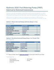
Fuel System<br />
The <strong>Hydronic</strong> M<strong>II</strong> boxed unit is most commonly provided with the<br />
fuel metering pump mounted inside the box. This is to reduce<br />
installation time and to protect the pump from corrosion. If specifications<br />
cannot be met the pump must be mounted externally.<br />
See illustration for connections and specifications. All parts<br />
necessary to do the installation are included in the kit as shown.<br />
Note: Fuel line limits must not be exceeded.<br />
Ensure that the following conditions are met.<br />
Fuel System Tolerances<br />
12<br />
Bottom of the fuel metering pump must be within a height<br />
of 2ʼ6” of the bottom of the fuel pick-up pipe.<br />
Fuel metering pump must be within a total distance of<br />
6ʼ6” from the fuel pick-up pipe.<br />
Pressure runs of less than 1.3 mtrs (50”) use only 3.5mm<br />
rubber (360 75 300)<br />
Control and Safety Devices<br />
Emergency shutdown – EMERGENCY OFF<br />
If an emergency shutdown – EMERGENCY OFF – is necessary<br />
during operation, proceed as follows:<br />
• Switch the heater off with the control<br />
• pull the fuse out<br />
• disconnect the heater from the battery.<br />
Max. 2ʼ6”<br />
FUEL<br />
TANK<br />
Max. 6ʼ6”<br />
2<br />
Max. 6ʼ6”<br />
3<br />
1<br />
2<br />
4<br />
Max. 20”<br />
6<br />
5<br />
Fuel Line<br />
• Route fuel lines from the fuel pick-up pipe to the heater.<br />
• Use <strong>Espar</strong> approved fuel lines.<br />
• Other sizes or types of fuel lines may inhibit proper fuel flow.<br />
• Make proper butt joints using clamps and connector pieces<br />
as shown<br />
• Use a sharp utility knife to cut plastic fuel lines to avoid burrs.<br />
7<br />
Note: Butt joints and clamps on all connections.<br />
6<br />
5<br />
1. Fuel Pick-Up Pipe<br />
2. 11mm Clamp<br />
3. 5.0mm Fuel Line<br />
4. Fuel Metering Pump<br />
5. 9mm Clamp<br />
6. 3.5mm Rubber Connector<br />
7. 2.0mm White Plastic Fuel Line<br />
See notes if length is less than<br />
1.3 mtr (50”)
Installation Procedures<br />
Fuel Metering Pump Installation<br />
If the pump needs to be mounted externally follow these guidelines:<br />
• Choose a protected mounting location close to the fuel pickup<br />
pipe and heater.<br />
• Using the bracket and rubber mount provided, install pump as<br />
shown.<br />
Note: Proper mounting angle of the pump is necessary to<br />
allow any air or vapor in the fuel lines to pass through<br />
the pump rather than cause a blockage.<br />
Fuel Pick-Up Pipe Installation (Standard Pick-Up)<br />
• Choose a protected mounting location close to the pump and<br />
heater. A spare fuel sender gauge plate provides an<br />
ideal mounting location.<br />
• Drill the mounting holes as shown.<br />
• Cut the fuel pick-up pipe to length.<br />
• Mount the fuel pick-up pipe as shown<br />
• Lower the fuel pick-up pipe (with reinforcing washer) into<br />
the tank using the slot created by the two 0.6cm (1/4”) holes.<br />
• Lift the assembly into position through the 2.5cm (1”) hole.<br />
• Assemble the rubber washer, metal cup washer and nut.<br />
Note: Drill the two (1/4”) holes first.<br />
Fuel Pick-Up Pipe<br />
Nut<br />
Sheet Metal Washer<br />
Rubber Gasket<br />
Steel Safety Washer<br />
Holding Tabs<br />
Allow 4” from fuel pick-up<br />
to tank bottom. Allow<br />
only 1” for flat bottom<br />
tanks.<br />
End tip of the fuel pickup<br />
pipe should have<br />
angle so as to avoid<br />
picking up dirt and<br />
subsequent blockage<br />
Note: Some pick-up pipes can be installed by either drill or<br />
NPT.<br />
( Optional Pick-Up Pipe with NPT fitting )<br />
• Remove an existing plug from the top of<br />
the fuel tank.<br />
• Cut the fuel pick-up pipe to length.<br />
• Secure the fuel pick-up pipe into position<br />
using the combined NPT compression<br />
fitting as shown<br />
Note: NPT fittings are available in various sizes<br />
(Refer to parts catalogue).<br />
13
Installation Procedures<br />
Electrical Connections<br />
Caution: To avoid potential short circuit damage during installation,<br />
insert main fuse into the power harness after<br />
all electrical connections are complete.<br />
A) Power Harness...................................................................<br />
Note: Wire must be inserted into fuse holder prior to<br />
terminating.<br />
B) Switch Harness..................................................................<br />
C) Fuel Metering Pump Harness...........................................<br />
14<br />
-<br />
7 Day Timer<br />
+<br />
A<br />
• 2 core harness (red, brown).<br />
• Connect red wire to fuse link and terminal.<br />
• Attach ring terminal to vehicle battery (+).<br />
• Connect brown wire to vehicle battery (-) using ring<br />
terminal provided.<br />
• Insert fuse. (15A-24V, 20A-12V)<br />
• 4 core harness (red, brown, yellow, blue/white)<br />
• Run to location of switch. Make terminal connections at<br />
switch. <strong>Espar</strong> has different available switches.<br />
See switch instructions for more information.<br />
• 2 core harness (green, green).<br />
• Fuel Metering Pump Harness is pre-connected when<br />
box is provided with pump pre-mounted.<br />
• If mounted externally, connect wires to fuel metering<br />
pump using connector and terminals supplied, with the<br />
heater - (no polarity required).<br />
B C<br />
7 Day Timer<br />
switch harness<br />
Shown is a <strong>Hydronic</strong> M<strong>II</strong> boxed version, 12 volt with<br />
Standard - Power, Switch, Fuel Metering Pump harnesses<br />
and optional 7 day timer.<br />
Other timers or switch options are available.<br />
Easy Start Mini Timer<br />
Programable Push and<br />
Timer Pull Switch<br />
I AUTO O RUN P<br />
P M<br />
1 2 3 4 5 6 7<br />
P 1...7 h m<br />
R<br />
Note: All harnesses should be cut to length.<br />
All exposed electrical connections should be coated<br />
with protective grease.
Installation Procedures<br />
Exhaust Connection<br />
A 30 mm flexible tube exhaust pipe with a length of 1m long is supplied<br />
with the kit for the exhaust. An exhaust clamp is needed to<br />
secure the exhaust to the the heater. The exhaust hose cannot be<br />
any longer than 1.8 m. Connect the exhaust as follows:<br />
• Connect the exhaust pipe to the exhaust port on the heater and<br />
attach with clamp provided. Feed the exhaust pipe through the<br />
silicone (white) grommet on the bottom of the box.<br />
• Run exhaust to an open area to the rear or side of the vehicle so<br />
that fumes can not build up and enter the passenger compartment<br />
or the heater combustion air intake.<br />
• Install exhaust pipe with a slight slope or drill a small hole in the<br />
lowest point to allow water to run off. Any restriction in exhaust<br />
will cause operational problems.<br />
• Route the exhaust pipe from the heater using holders provided.<br />
Caution: Run exhaust so that it cannot be plugged by dirt, water<br />
or snow. Ensure the outlet does not face into the vehicle<br />
slip stream.<br />
Note: 1. Exhaust hose cannot be any longer than 2m (80”)<br />
2. Minimum length 0.2 m (8”)<br />
3. Air intake silencer always needed.<br />
ATTENTION: Refer to pg. #3 for High altitude capabilities.<br />
Route exhaust beyond the skirt of the cab and outside of the<br />
frame area. Route exhaust so that the exhaust fumes cannot<br />
enter the passenger compartment. Failure to comply with this<br />
warning could result in Asphyxiation.<br />
Holding clamps<br />
Intake Connection<br />
Combustion air must be drawn in from the outside of vehicle.<br />
The combustion air opening must be kept free at all times.<br />
• Connect the air intake pipe to the intake port on the heater<br />
and secure with clamp provided.<br />
Caution: Do not install the intake opening facing the vehicle<br />
slipstream. Ensure that the opening cannot<br />
become clogged with dirt or snow and that any<br />
water entering the intake can drain away.<br />
Flexible Exhaust<br />
& Air intake hose<br />
cannot be any<br />
longer than<br />
Max 2m (80”)<br />
Warning: Asphyxiation Hazard Warning: Fire Hazard<br />
Exhaust & Intake<br />
Clamps<br />
P/N 25 1786 80 02 00<br />
Air Intake silencer<br />
Always needed<br />
End Sleeve<br />
The exhaust is hot, keep a minimum of 5cm (2”) clearance<br />
from any heat sensitive material. Failure to comply with this<br />
warning could result in fire and serious injury.<br />
15
Installation Procedures<br />
Operating Switches<br />
A 7 Day Timer, a Push/Pull switch, a Programmable Timer or an<br />
easy start timer are available for the heater.<br />
7 Day Timer Instructions<br />
The 7 Day Timer has been designed to provide a simple means<br />
to control the operation of the heater system and to include the<br />
capability for diagnostics. This timer connects to the diagnostic<br />
circuit of the heater. The timer then displays any heater fault<br />
codes in three digit number form automatically. The timer allows<br />
for pre-selection of turn on time, up to 7 days in advance, as well<br />
as an option for run times up to 2 hours before automatically turning<br />
off. In addition, there is an on/off switch for manual operation.<br />
By default the timer is pre-set by <strong>Espar</strong> to operate for two hours.<br />
Refer to instructions provided with timer for setting options.<br />
• Mount bezel into dash and insert timer or use <strong>Espar</strong>ʼs optional<br />
mounting bracket and secure to dash.<br />
• Use hardware supplied for connections.<br />
• Connect the switch harness to the connector at the heater and<br />
run harness to switch location. (Harness should be neatly<br />
routed and secured under dashboard).<br />
• Cut harness to length and terminate wires. Attach using connectors<br />
provided.<br />
• Refer to timer instructions for other wiring options.<br />
Note: If installing a remote starter, refer to remote starter<br />
instructions before terminating wires.<br />
Option #1: Dash lights to timer - connect wire between dash<br />
lights circuit and timer at terminal #1.<br />
Note: The timer display is automatically illuminated while the<br />
heater is operating. Connecting pin 1 to the vehicle<br />
dim- mer switch will allow the timer display to illuminate with<br />
the vehicles dash lights.<br />
16<br />
Bezel<br />
Mounting Bracket & Bezel<br />
P/N 25 1482 70 01 00<br />
Mounting Bracket<br />
I AUTO O RUN P<br />
P M<br />
1 2 3 4 5 6 7<br />
P 1...7 h m<br />
R<br />
a4)<br />
a3)<br />
a5)<br />
a2)<br />
Red<br />
Yellow<br />
Brown<br />
Blue<br />
Option #2<br />
Option #1<br />
Yellow<br />
Blue<br />
Red<br />
Brown<br />
12 11 10 9 8 7 6 5 4 3 2 1<br />
TRS<br />
DIAG<br />
Option #2: Operate heater continuously - connect wire from<br />
ignition circuit to terminal #10.<br />
Note: An alternative to connecting pin 10 to the vehicle<br />
ignition accessories “On” circuit may also be considered<br />
for some applications where extended run<br />
times are desired. Connecting pin 10 with the red<br />
wire will enable the heater to run continuously on<br />
manual mode.<br />
Operating Instructions<br />
Setting Time and Weekday<br />
Push button once 12:00 will begin to flash (this will occur<br />
upon initial hook up to power).<br />
Using or set the present time of day (24 hour clock).<br />
When the time stops flashing the time has been stored.<br />
The weekday will now begin to flash.<br />
Use or to set the present weekday.<br />
When the weekday stops flashing the weekday has been stored.<br />
When the vehicle ignition is turned “on” the time display will<br />
appear, if optional connection on pin 10 is insatlled.<br />
When the vehicle ignition is turned “off” the timer display will go<br />
off after 15 seconds.<br />
Changing the Time or Day<br />
Push and hold button until the time display begins to flash.<br />
Continue to set the time as listed in setting time and weekday.<br />
Using the Timer with the Vehicle Ignition “Off”<br />
Push button.<br />
will appear on the display as well as the operation countdown<br />
timer.<br />
The running time is factory set to maximum of 120 minutes.<br />
This running time can be reset once or permanently as desired.<br />
Adjusting Preheat Time Once<br />
Press button.<br />
The will appear in the display and the preselected run<br />
time will appear in the display (maximum time of 120 minutes).<br />
Use the or to adjust the desired run time.<br />
Adjusting the <strong>Heater</strong> Preheat Time Permanently<br />
(Maximum Preheat Time of 120 minutes)<br />
Push and hold (about 3 seconds) until the display lights up<br />
and flashes. Release button.<br />
Use or to set the new fixed preheat time.<br />
When the display goes off the new preheat time is set.<br />
Note: At the end of a preheat cycle the timer will turn the<br />
heater off. The heater will complete a cool down<br />
cycle and turn itself off.<br />
P
Installation Procedures<br />
Using the <strong>Heater</strong> Manually with the Vehicle Accesory “On”<br />
(Optional wire on pin 10 is connected to the ignition lock)<br />
Push buton.<br />
The symbol will appear in the display next to the time of day.<br />
The time of day will remain displayed during ignition on operation.<br />
The heater will function continually as long as the vehicle ignition<br />
is “On”.<br />
When the vehicle ignition is turned “Off” the heater will continue<br />
to operate for an additional 15 minutes.<br />
The run time can be altered by pressing the or buttons.<br />
The heater can be turned off by pressing button.<br />
Set Preheat Times into Memory<br />
Press button until the desired memory location is shown in<br />
the display (Three memory locations are available).<br />
Using the or buttons set the desired preheat start time<br />
of day.<br />
When the time stops flashing the time of day is set.<br />
Using the or buttons set the desired day of the week.<br />
When the day of the week stops flashing the day is set.<br />
To Use Preset Start Times<br />
Press the button until the desired memory location appears<br />
in the display.<br />
The heater will start at the day and time displayed.<br />
The display will go off in 15 seconds. The memory location<br />
number will stay displayed (1, 2 or 3).<br />
Note: When preset is chosen this symbol will flash red.<br />
To Turn <strong>Heater</strong> “Off” - All Modes<br />
Press the button once.<br />
The heat signal to the heater will be turned “Off”.<br />
The heater will do a normal cooldown and turn itself “Off”.<br />
Note: · This timer is equipped to display fault code numbers if<br />
the heater should shut down due to an operating fault.<br />
The fault code will show in the timer display next to the<br />
flashing heat wave symbol. This applies to all current<br />
model heaters when the blue diagnostic wire is connected.<br />
· If the timer is purchased without the harness kit, the<br />
following heaters will need a load relay intalled (D8Lc,<br />
D7W, D12W, D24W and D30W), These heaters carry a<br />
load on the switch wire. (i.e. fuel metering pump or noid<br />
sole valve).<br />
· An outside temperature sensor is available as an option.<br />
Wiring Connections at Connector<br />
Terminal 1 Power from vehicle dash lights.<br />
Terminal 2 <strong>Heater</strong> switch wire - Yellow wire.<br />
Terminal 4 Connect to vehicle ground.<br />
Terminal 6 Temperature setting “+” (air only).<br />
Terminal 8 <strong>Heater</strong> diagnostic lead - blue wire.<br />
Terminal 9 Temperature setting “-” (air only).<br />
Terminal 10 To vehicle “ACC” accessory for<br />
continuous overnight use, and for<br />
unlocking ECU.<br />
Terminal 11 Positive power from heater - red “+”.<br />
Terminal 12 Ground lead from heater - brown “-”.<br />
Terminal 3,5,7 Left blank, not required.<br />
Control Unit Locking<br />
The control unit may becomed locked due to one of the following<br />
conditions:<br />
1. Overheat – If the heater overheats three times in succession,<br />
fault message F15 is displayed and the<br />
control unit is locked.<br />
2. Too many failed start attempts - If the heater performs<br />
many start attempts in succession (i.e. Fault 52), fault<br />
messsage F50 is displayed and the control unit is locked.<br />
Unlocking Control Units and Erasing Fault Memory<br />
Note: The electrical connection for the ignition / accessory<br />
wire to the timer terminal #10 must be in place.<br />
1. Turn on the vehicle ignition to activate timer display.<br />
2. Press the key. The current fault code (i.e. F15 or F50)<br />
is now displayed.<br />
3. Press the key and hold it down and press the key<br />
within two seconds. The timer is now in the retrieval mode.<br />
4. Turn off the ignition.<br />
5. Press the key and hold it down and press the key<br />
within two seconds and hold it down.<br />
6. While holding down keys, turn ignition on and wait<br />
until the following display appears:<br />
7. Press the key to turn the heater off.<br />
8. Press the key to turn the heater on.<br />
9. Repeat step three. The following display appears:<br />
10.The control unit lock is cancelled after three seconds<br />
and the heater starts.<br />
Retreaving the Stored Fault Codes<br />
1. Press the key. The heater is switched on.<br />
2. Press the key and hold it down and press the key<br />
within two seconds. The current fault code is now displayed<br />
(Example: AF:64).<br />
3. The stored fault codes (maximum of 5) can now be<br />
retrieved<br />
Note: Consult the Troubleshooting and Repair manuals for<br />
code definition and corrective action. If the heater is<br />
not being operated using the 7-day timer, fault code<br />
retrieval can be obtained using the “Fault Code<br />
Retrieval Device”, part number: 20 2900<br />
70 50 20.<br />
17
Installation Procedures<br />
Push/Pull Switch<br />
• Mount switch in a location where it is easily accessible<br />
• Mount using hardware supplied<br />
• Connect the switch harness to the connector at the heater<br />
and run the harness to the switch location<br />
• Cut harness to length at the switch and install terminals<br />
• Connect wiring as described below<br />
Note: Switch light glows when pulled out and is off when<br />
pushed in.<br />
Brown- 31 Power from battery “-”<br />
Red- K(15) Power from battery “+”<br />
Yellow-15(K) Switch control to the heater<br />
Blue/White Diagnostic from heater (disregard - tape end<br />
and tie off to the side)<br />
P/N 5670007 (12v)<br />
P/N 5670008 (24v)<br />
Programmable Timer<br />
P/N 5670433 (12v)<br />
P/N 5670434 (24v)<br />
18<br />
I AUTO O RUN P<br />
P M<br />
1 2 3 4 5 6 7<br />
P 1...7 h m<br />
R<br />
IMPORTANT: This electronic timer has a maximum loading<br />
printed on the rating label and under no circumstances<br />
should this be exceeded.<br />
Features:<br />
• Up to 8 ON and OFF switches a day/56 ON and OFF swit-<br />
ches per week.<br />
• Option to program individual days or 8 different weekday<br />
groups.<br />
• Minimum switching period of one minute<br />
• Summer/Winter time changeover<br />
• Easy to read LCD display<br />
• Manual Override button<br />
• Battery Back-up<br />
Note: As soon as you have connected 12 or 24 volts you<br />
will have to push down the RESET button and set<br />
time to activate the timer.<br />
Setting the time<br />
- Slide right switch to to set time.<br />
- Press 1….7 button until arrow points to current day<br />
(1=Monday, 2=Tuesday, etc.). Press the “ h ” and“ m ” buttons to set<br />
the hours and minutes. The “PM” indicator shows noon to<br />
11:59 p.m.<br />
- Slide right switch to “RUN”.<br />
Programming of Switching Times<br />
The Auto Time Switch has the capacity for 8 ON/OFF switches.<br />
By using the blocks of days available, you can save program<br />
capacity. The block days are:<br />
MO, TU, WE, TH, FR, SA, SU – Individual days of the week<br />
MO, TU, WE, TH, FR<br />
SA, SU<br />
MO, TU, WE, TH, FR, SA<br />
MO, WE, FR<br />
TU, TH, SA<br />
MO, TU, WE<br />
a3)<br />
a5)<br />
a4)<br />
Yellow (Signal to <strong>Heater</strong>)<br />
Brown (-)<br />
Red (+)<br />
Programmable Timer Instructions<br />
- To program ON or OFF time slide the right switch to .<br />
A “ ” appears in the bottom right hand.<br />
corner and a bulb icon is displayed indicating an ON time is<br />
ready to be programmed in memory “ ”.<br />
Press “P” button until desired ON or OFF time program is<br />
selected. (NOTE: Odd numbers indicate ON times and Even<br />
numbers indicate OFF times. When an OFF time is ready to be<br />
programmed there is no bulb icon present. Every cycle must<br />
have a programmed ON time and a programmed OFF time or<br />
the program will not execute.)<br />
- Press 1....7 button until arrows point to selected day(s) you<br />
want this ON cycle to occur.<br />
- Press “ h ” and “ m ” buttons to show switch-on time, noting<br />
the “PM” indicator.<br />
5<br />
4 5670433 - 12 Volt<br />
5670434 - 24 Volt<br />
3<br />
2<br />
Programmable<br />
Timer<br />
Note: to save time you can set up each on/off cycle;<br />
- A) to be unique for each individual day, or<br />
- B) for Monday to Friday (days 1 to 5), or<br />
- C) for weekends only (days 6 & 7), or<br />
- D) for all days except Sunday (days 1 to 6) , or …<br />
- E) the entire week at one time. This can save a lot<br />
of time when programming the “on” and “off” cycles.<br />
1
Notes:<br />
19
<strong>Heater</strong> Operation<br />
Pre-Start Procedures<br />
Upon completion of installation prepare the heater as follows:<br />
• Check all fuel, electrical and plumbing connections.<br />
• Refill the engine coolant.<br />
• Bleed air from the coolant system by running the engine and<br />
refilling the antifreeze as needed. Resecure heater hose.<br />
• Run engine to further bleed the system<br />
• Top up engine coolant.<br />
Start Up<br />
Once switched on, the following sequence occurs:<br />
• Control unit does a systems check (flame sensor, temperature,<br />
and various other control unit checks).<br />
• <strong>Water</strong> pump starts circulating coolant fluid.<br />
• Combustion air blower starts.<br />
• Glow pin begins to preheat 20-30 secs.<br />
• After about 20-3 0 seconds the Fuel Metering Pump starts delivering<br />
fuel and the combustion air blower ramps up gradually.<br />
• Once ignition takes place the flame sensor alerts the control<br />
unit and the control unit shuts off the glow pin (ignition time:<br />
1.5 - 2 minutes).<br />
Note: If the heater fails to start the first time it will automatically<br />
attempt a second start. If unsuccessful the heater<br />
will shut down completely.<br />
Note: On initial start up the heater may require several<br />
start attempts to self prime the fuel system.<br />
Heating Mode<br />
At the initial start the heater is operated with the “POWER” stage<br />
until the water temperature exceeds the “POWER” / “HIGH”<br />
changeover threshold.<br />
HYDRONIC M8 / M10<br />
Then, depending on the heat requirement, the heater switches to<br />
the “HIGH – MEDIUM – LOW – STAND BY” stages.<br />
If the heating requirement in the “LOW” stage is so small that the<br />
cooling water temperature reaches 85 °C, the heater switches<br />
from “LOW” to “STAND BY”.<br />
HYDRONC M12<br />
Then, depending on the heat requirement, the heater switches to<br />
the “HIGH – MEDIUM 1 / MEDIUM 2 / MEDIUM 3 – LOW –<br />
STAND BY” stages.<br />
If the heating requirement in the “LOW” stage is so small that the<br />
cooling water temperature reaches 85 °C, the heater switches<br />
from “LOW” to “STAND BY”.<br />
This is followed by the after-run with additional after glowing of the<br />
glow plugs (like when heater is switched off).<br />
After the cooling water has cooled to approx. 70 °C the<br />
HYDRONIC M8 / M10 heater starts in the “MEDIUM” stage, the<br />
HYDRONC M12 heater in the “MEDIUM 1” stage.<br />
If the cooling water temperature reaches approx. 55 °C the<br />
temperature sensor switches the vehicle fan on.<br />
Temperature Drop<br />
Temperature drop only becomes active while the vehicle is runing<br />
and if the heater is switched on. The control stages are reached<br />
earlier and the heaterʻs control action is adjusted to the lower heat<br />
requirement.<br />
20<br />
The temperature can be lowered by connecting the positive<br />
cable (+) to connector S2, terminal C3 of the heater (see circuit<br />
diagrams).<br />
Switching Off<br />
With the switching off the heater starts the after-run of<br />
180 sec. During the after-run the first glow plug is switched<br />
on after 90 seconds for a period of 45 seconds,<br />
then the second glow plug is switched on until the end<br />
of the after-run.<br />
Safety Equipment<br />
The heater is equipped with the following control and safety<br />
devices.<br />
• If the heater does not ignite within 74 seconds after the fuel<br />
starts to pump, the start is repeated.<br />
If the heater still does not ignite after another 65 seconds of<br />
fuel being pumped, the heater is automatically shut down.<br />
After an unacceptable number of failed start attempts, the<br />
control box is locked.*<br />
• If the flame goes off by itself during operation, the heater is<br />
restarted.<br />
If the heater does not ignite within 74 seconds after the fuel<br />
starts to pump again, the heater is automatically shut down.<br />
The shutdown on faults can be cancelled by briefly switching<br />
off and on again.<br />
• In the case of overheating (e.g. water shortage, poorly ventilated<br />
cooling water circuit), the overheating sensor triggers,<br />
the fuel feed is interrupted and the heater is automatically<br />
shut down.<br />
Once the cause of the overheating has been eliminated, the<br />
heater can be re-started by switching it off and on again<br />
(provided that the heater has cooled down sufficiently, cooling<br />
water temperature < 70 °C).<br />
After the heater has been shut down due to overheating an<br />
unacceptable number of times, the control box is locked.*<br />
* The ECU can be unlocked and the fault can be displayed<br />
with:<br />
• EasyStart.<br />
• Diagnostics Unit.<br />
• EDiTH diagnostics software.<br />
For operation and fault list, please refer to the enclosed<br />
operating instructions or these troubleshooting and repair<br />
instructions.<br />
• If the lower or upper voltage limit is reached, the heater<br />
will shut down.<br />
• The heater does not start up if the electric cable to the<br />
metering pump is not connected.<br />
• If one of the two glow plugs is defective, the start sequence<br />
takes place with one glow plug only .<br />
• The speed of the blower motor is continuously monitored.<br />
If the blower motor does not start up, if it is blocked or if the<br />
speed differs by > 12.5 % of the desired speed, the heater<br />
will automatically shut down after 60 sec.<br />
• The function of the water pump is continuously monitored.<br />
Warning:<br />
The heater must be switched off while any<br />
fuel tank on the vehicle is being filled.<br />
The heater must not be operated in<br />
garages or enclosed areas.
<strong>Heater</strong> Operation<br />
<strong>Heater</strong> Wiring<br />
The heater is to be connected up electrically according to the<br />
EMC directives.<br />
Caution:<br />
EMC can be affected if the heater is not connected up correctly.<br />
For this reason, comply with the following instructions:<br />
• Ensure that the insulation of electrical cables is not damaged.<br />
Avoid:<br />
chafing, kinking, jamming or exposure to heat.<br />
• In waterproof connectors, seal any connector chambers not<br />
in use with filler plugs to ensure they are dirt-proof and waterproof.<br />
• Electrical connections and ground connections must be free<br />
of corrosion and firmly connected.<br />
• Lubricate connections and ground connections outside the<br />
heater interior with contact grease.<br />
Note: Comply with the following when wiring the heater and the<br />
control unit: fuses and controlers.<br />
• Electrical leads, must be positioned in the vehicle so that they<br />
can function perfectly under normal operating conditions without<br />
impairment (e.g. due to heat exposure, moisture, etc.).<br />
• The following wire gauge are to be used between the battery<br />
and heater.<br />
This ensures that the max. allowable voltage drop in the<br />
cables does not exceed 0.5 V for 12 V or 1 V for 24 V<br />
rated voltage.<br />
Cable cross-sections for a cable length (plus cable + minus<br />
cable) of:<br />
– up to 5 m (plus cable + minus cable) = 10 AWG<br />
– from 5 m up to 8 m (plus cable + minus cable) = 8 AWG<br />
• If the ( + ) cable is to be connected to the fuse box, the<br />
vehicle's cable from the battery to the fuse box must also be<br />
included in the calculation for the total cable length and<br />
re-dimensioned if necessary.<br />
• Insulate unused cable ends.<br />
If replacing the HYDRONIC 10 / M with the HYDRONIC M-<strong>II</strong>, the<br />
cable harness installed in the vehicle is retained and continues to<br />
be used, it is necessary to remove the 12-pin connector using the<br />
terminal removal tool and to rewire it according to the following<br />
table.<br />
12-pin Connection Pin Assignment<br />
Connection<br />
Cable harness<br />
Rewiring<br />
HYDRONIC M<br />
12-pin connector<br />
Cable colour HYDRONIC M HYDRONIC M-<strong>II</strong><br />
PIN<br />
PIN<br />
Metering pump green<br />
Terminal (-) brown<br />
Terminal (+) red<br />
Plus signal<br />
main battery switch<br />
Plus signal<br />
Solenoid valve relay<br />
white / red<br />
Diagnosis blue<br />
Plus signal<br />
ADR auxiliary drive<br />
Third party control<br />
<strong>Water</strong> pump<br />
–<br />
violet<br />
Blower relay red / yellow<br />
D+<br />
for ADR operation<br />
–<br />
violet / green<br />
Temperature drop –<br />
<strong>Heater</strong> ON yellow<br />
Connector is shown<br />
from the lead entry<br />
side.<br />
C 4<br />
A1<br />
C 3<br />
A2<br />
C 2<br />
A3<br />
C 1<br />
A4<br />
B 4<br />
B1<br />
B 3<br />
B4<br />
B 2<br />
B3<br />
B1<br />
B2<br />
remains<br />
unused<br />
A 4<br />
C1<br />
A 3<br />
C2<br />
A 2<br />
C3<br />
A 1<br />
C4<br />
21
<strong>Heater</strong> Operation<br />
Parts list for wiring diagram, <strong>Hydronic</strong> M-<strong>II</strong> - 12 Volt / 24 Volt<br />
1.1 Blower motor<br />
1.2 Glow pin I<br />
1.2.1 Glow pin <strong>II</strong> (optional 12 kW)<br />
1.5 Overheating sensor<br />
1.12 Flame sensor<br />
1.13 Temperature sensor<br />
2.1 Control unit<br />
2.2 Fuel metering pump<br />
2.5.7 Relay, vehicle blower (fan)<br />
2.5.18 Relay, changeover water circuit<br />
(To be fitted by customer if required)<br />
2.7 Main fuse 12 volt = 20A<br />
24 volt = 15A<br />
2.7.1 Fuse, control option 5A<br />
2.7.5 Fuse, vehicle blower (fan) 25A<br />
2.12 <strong>Water</strong> pump<br />
5.1 Battery<br />
5.10 Vehicle blower (fan)<br />
a) Connection to 7 day timer, programmable timer, easy start or<br />
push pull switch<br />
b) <strong>Water</strong> circuit change-over: Relay makes contact at 68°C and<br />
breaks contact at 63 °C water temperature (with temperature<br />
drop 58 °C / 45 °C)<br />
c) Temperature drop<br />
x) Disconnect cable<br />
a2) Diagnosis<br />
a3) Switch on signal<br />
a4) Power supply plus<br />
a5) Power supply minus<br />
Connectors and bush holdings are shown from the cable<br />
inlet side.<br />
Connector pin assignment: 12-pin connector (external).<br />
22<br />
PIN-No. Connection<br />
A1 Dosing osing<br />
pump<br />
B1 Solenoid valve, optional<br />
C1 Relay, blower<br />
A2 Battery ( - )<br />
A3 Battery ( + )<br />
B3 TRS signal (ADR)<br />
C3 Temperature drop<br />
B4 Diagnosis<br />
C4 <strong>Heater</strong> ON
<strong>Heater</strong> Operation<br />
<strong>Hydronic</strong> M-<strong>II</strong>, Wiring Diagram - 12 Volt / 24 Volt<br />
2.1<br />
B3<br />
B3<br />
S3<br />
2.2<br />
1 1 14 10 7 4 12 13 1 2 8 5 6 3 9<br />
1.2.1 1.2 1.5 2.12 1.13 1.12 1.1<br />
Brown / Green<br />
Brown<br />
Green<br />
Brown<br />
Red<br />
White / Red<br />
White<br />
Brown<br />
White<br />
Brown<br />
Red<br />
White / Red<br />
Brown / Black<br />
Yellow<br />
Blue / White<br />
Blue<br />
Blue / White<br />
Brown<br />
Pink<br />
Green<br />
Orange<br />
Red / Yellow<br />
B1<br />
B2<br />
S2<br />
5.10<br />
x)<br />
2.5.7<br />
2.7<br />
2.7.5<br />
2.7.1<br />
B1 B2 B3 S2 S3<br />
c)<br />
Yellow<br />
A1<br />
A2<br />
A3<br />
A4<br />
B1<br />
B4<br />
B3<br />
B2<br />
C1<br />
C2<br />
C3<br />
C4<br />
Brown<br />
Black/Violet<br />
Black<br />
Red<br />
Brown<br />
Red / Yellow<br />
b)<br />
2.5.18<br />
Red<br />
Red<br />
Red<br />
b)<br />
Red<br />
Brown<br />
Brown<br />
Optional<br />
White/Red<br />
Blue/White<br />
Yellow<br />
Red<br />
Brown<br />
5.1<br />
a1)<br />
a2)<br />
a3)<br />
a4)<br />
a5)<br />
a)<br />
23
<strong>Heater</strong> Operation<br />
<strong>Hydronic</strong> M-<strong>II</strong>, Controler Options<br />
24<br />
a3)<br />
a5)<br />
a4)<br />
a4)<br />
a3)<br />
a5)<br />
RED<br />
YELLOW<br />
BROWN<br />
0<br />
0<br />
15 (K)<br />
K (15) 31<br />
Option<br />
a4) Red<br />
a3) Yellow<br />
Yellow<br />
a5) Brown<br />
a2) Blue<br />
TRS<br />
Blue<br />
DIAG<br />
Red<br />
Brown<br />
Option #2<br />
Yellow (Signal to <strong>Heater</strong>)<br />
5<br />
4 5670433 - 12 Volt<br />
5670434 - 24 Volt<br />
3<br />
Brown (-)<br />
2<br />
Programmable<br />
Timer<br />
Red (+)<br />
1<br />
LCD<br />
9<br />
Brown / White<br />
8<br />
Grey<br />
Grey<br />
7<br />
White / Red<br />
Grey / Black<br />
a1)<br />
6<br />
Blue / White<br />
Blue / White<br />
a2)<br />
5<br />
Violet<br />
4<br />
Brown<br />
Brown<br />
a5)<br />
3<br />
Yellow<br />
2<br />
a4)<br />
Red<br />
Red<br />
1<br />
B1 S1<br />
12 11 10 9 8 7 6 5 4 3 2 1<br />
Optional On/Off Switch<br />
Push / Pull Switch<br />
P<br />
7 Day Timer<br />
Programmable Timer<br />
Easy Start T
Maintenance, Troubleshooting & Repairs<br />
Subtitle Periodic Right Maintenance Page<br />
• Check coolant hoses, clamps, and make sure all valves<br />
are open. Maintain the engine manufacturers recommended<br />
coolant level and ensure that the heater is properly bled after<br />
service on or involving the coolant system.<br />
• Visual check of all fuel lines for leaks. Check and if necessary<br />
replace fuel filter inserts.<br />
• Visual check of electrical lines and connections for corrosion.<br />
• Run your heater at least once a month during the year (for a<br />
minimum of 15 minutes).<br />
• Maintain your batteries and all electrical connections in good<br />
condition. With insufficient power the heater will not start.<br />
Low and high voltage cutouts will shut the heater down automatically.<br />
• Use fuel suitable for the climate. Blending used engine oil<br />
with diesel fuel is not permitted.<br />
Troubleshooting<br />
Basic Troubleshooting<br />
In the event of failure there are several items which should be<br />
checked first before any major troubleshooting is done.<br />
Check:<br />
• Fuses.<br />
• Electrical lines and connections<br />
• Interference in Combustion air and Exhaust pipes.<br />
• Fuel in the tank.<br />
• Battery voltage on heater side of harness<br />
• Coolant flow<br />
Self Diagnostics<br />
The heater is equipped with self diagnostic capability. You can<br />
retrieve information on the heaters last 5 faults using the <strong>Espar</strong> 7<br />
day timer, <strong>Espar</strong>ʼs Fault Code Retrieval Device or ISO adapter<br />
and computer.<br />
Multifunction<br />
<strong>Espar</strong>ʼs 7 day timer has a fault code<br />
retrieval device built into the unit. This<br />
function automatically activates if the<br />
heater is experiencing problems.<br />
• Fault codes appear on the LCD display screen.<br />
• Codes can then be translated from the charts on the following<br />
pages.<br />
• Pg 10 - 17 for more detailed instructions.<br />
Fault Code Retrieval Device<br />
Equipment Face and Controls<br />
Symbols seen on the display<br />
face are as follows:<br />
AF Actual fault.<br />
F1-F5 Up to five stored faults can be accessed.<br />
The AF and F1 are the same.<br />
This sign is displayed when the heater is in operation.<br />
DIAG The word (Diagnostic) will come on when the diagnostic<br />
number is requested.<br />
000 Three digit diagnostic fault code number.<br />
Hook Up<br />
• Disconnect the main harness from heater and insert adapter<br />
cable harness between them.<br />
• Connect adapter cable to the cable loom of the Fault code<br />
retrieval device.<br />
• Start diagnostic unit - switch heater on from switch.<br />
Instructions:<br />
• Switch the fault code retrieval device on and wait 10 seconds.<br />
• Press the "D" button.<br />
• Wait 3-5 seconds for the current fault code to appear (AF).<br />
• To review the previous faults use the arrow buttons<br />
(F1= Most Recent, F5= Oldest).<br />
• To erase the faults that are in memory press both "L" keys at<br />
the same time.<br />
• See the fault code chart on following pages for code number<br />
descriptions.<br />
Diagnostic Adapter<br />
P/N 25 2800 70 1004<br />
Fault code<br />
retrieval device<br />
P/N 20 2900 70 5020<br />
25
Maintenance, Troubleshooting & Repairs<br />
Fault Code Fault Description Causes / Repair<br />
— — — Diagnosis not possible • Adapter cable not connected properly.<br />
• Diagnostic connection damaged.<br />
• Test ECU. Replace if necessary.<br />
000 No faults — —<br />
005 Warning • Check connection and / or lead for continuity, short circuit and<br />
Short circuit in "Burglar Alarm" output damage.<br />
009 ADR / ADR99 shutdown • Switch the heater off and then on again.<br />
010 Overvoltage cutoff Overvoltage applied to control box for at least 6 seconds.<br />
• Disconnect heater / cable harness plug-in connector, start<br />
the vehicle engine, measure the voltage. Connector B2, PIN<br />
A2 and A3:<br />
– If the voltage is >15 volt or >30 volt, check the generator<br />
regulator and / or the battery.<br />
011 Undervoltage cutoff Undervoltage applied to control box for at least 20 seconds<br />
without interruption.<br />
• Disconnect heater / cable harness plug-in connector, start the<br />
vehicle engine, measure the voltage. Connector B2, PIN<br />
A2 and A3:<br />
– If the voltage is Fault code 020.<br />
• Check control box.<br />
26
Maintenance, Troubleshooting & Repairs<br />
Fault Code Fault Description Causes / Repair<br />
020 Glow plug 1, interruption • Measure cold resistance of the glow plug at approx. 20°C<br />
ambient temperature – connector B1, PIN 7 and 10.<br />
021 Glow plug 1, overload / short circuit If the values are as follows the glow plug is ok, if the values<br />
downstream of (–) differ – replace the glow plug.<br />
022 Glow plug 1, short circuit downstream Measured value:<br />
of (+) • 12 volt – glow plug = 0.42 – 0.6 ohm<br />
• 24 volt – glow plug = 1.2 – 1.9 ohm<br />
– If the glow plug is ok, check the lead harness of the glow plug<br />
for continuity, short circuit and damage.<br />
023 Glow plug 2, interruption • Measure cold resistance of the glow plug at approx. 20°C<br />
ambient temperature – connector B1, PIN 11 and 14.<br />
024 Glow plug 2, overload / short circuit If the values are as follows the glow plug is ok, if the values<br />
downstream of ground differ – replace the glow plug.<br />
Measured value:<br />
• 12 volt – glow plug = 0.42 – 0.6 ohm<br />
• 24 volt – glow plug = 1.2 – 1.9 ohm<br />
– If the glow plug is ok, check the lead harness of the glow plug<br />
for continuity, short circuit and damage.<br />
025 Diagnostic line fault • Check diagnostics cable for continuity, short circuit and<br />
<strong>Heater</strong> remains ready for operation damage – connector B2, PIN B4.<br />
– if ok, check control box.<br />
026 Glow plug 2, short circuit downstream see fault code 023 / 024<br />
of (+)<br />
029 Glow plug 2, Ignition energy too low Glow plug 2 energy input is too low (< 2000 W)<br />
• Check glow plug for continuity, short circuit and damage.<br />
—> Fault code 023.<br />
• Check control box.<br />
031 Burner motor, interruption • Check the burner motor's connection leads for continuity, short<br />
circuit and damage – connector B1, PIN 3, 6 and 9.<br />
032 Burner motor, overload • Check burner motor for easy movement by manually rotating<br />
the impeller.<br />
– if not smooth running, remove the blockage.<br />
033 Burner motor, speed error / blocked – if ok, check control box / blower unit.<br />
034 Burner motor short circuit<br />
downstream of (+) or (–)<br />
037 <strong>Water</strong> pump not working • Check water pump.<br />
Apply voltage to the water pump – connector B1, PIN 12 and 13<br />
(power input = max. 4 A or 2 A)<br />
– If water pump does not rotate, replace water pump.<br />
– If water pump is ok –> check control box / blower unit.<br />
041 <strong>Water</strong> pump, interruption • Check the water pump's connection and lead harness for continuity,<br />
short circuit and damage – connector B1, PIN 12 and 13.<br />
– If ok, check water pump —> fault code 037.<br />
042 <strong>Water</strong> pump<br />
Overload short circuit <strong>Water</strong> pump running dry.<br />
043 <strong>Water</strong> pump • Vent heater (water shortage), check water flow rate.<br />
Overload downstream of +<br />
27
Maintenance, Troubleshooting & Repairs<br />
Fault Code Fault Description Causes / Repair<br />
047 Metering pump • Check the metering pump's connection and lead harness for<br />
Overload short circuit continuity, short circuit and damage – connector B2, PIN A1.<br />
– If ok, check the resistance of metering pump – setpoint value<br />
approx. 20 ohm.<br />
048 Metering pump interruption<br />
049 Metering pump<br />
Overload downstream of +Ub<br />
050 Too many attempted starts Control box locked due to repeated switching on in succession<br />
Control box is locked without flame detection (fault code 052).<br />
• Check fuel supply, exhaust and combustion air system.<br />
• Check glow plug –> see fault code 019 to 024 / 026 / 029.<br />
• Check flame sensor –> fault code 064 / 065.<br />
• Unlock the control box by deleting the fault memory.<br />
052 Exceeding of safety time No flame detected within the start phase. Flame sensor value <<br />
80°C, therefore automatic shutdown because safety time exceeded.<br />
28<br />
• Check fuel supply, exhaust and combustion air system.<br />
• Check glow plug –> see fault code 019 to 024 / 026 / 029.<br />
• Check flame sensor –> fault code 064 / 065.<br />
053 Flame cutout in <strong>Heater</strong> ignited (flame detected) and signals flame cutout during a<br />
"POWER" control stage power stage.<br />
• Check fuel quantity, blower speed, fuel supply, exhaust and combustion<br />
air system.<br />
054 Flame cutout in "HIGH" control stage • Check flame sensor –> fault code 064 / 065.<br />
055 Flame cutout in "Medium" control stage<br />
(D 8 W / D 10 W) "Medium1" control stage<br />
(D 12 W)<br />
056 Flame cutout in<br />
"Medium 2" control stage (D 12 W)<br />
057 Flame cutout in<br />
"Medium 3" control stage (D 12 W)<br />
058 Flame cutout in "LOW" control stage<br />
059 Too rapid rise in water temperature • Vent air from system, check water flowrate.<br />
• Check temperature sensor –> fault code 060 / 061<br />
060 Temperature sensor interruption Temperature sensor signals temperature value outside the<br />
measuring range.<br />
061 Temperature sensor short circuit • Measure the resistive value of the temperature sensor,<br />
Connector B1, PIN 1 and 2; for measured values. See page 44.<br />
– If temperature sensor ok, check connection leads for<br />
continuity, short circuit and damage.<br />
064 Flame sensor interruption Flame sensor signals temperature value outside the measuring<br />
range.<br />
065 Flame sensor short circuit • Measure the resistive value of the flame sensor – connector B1,<br />
PIN 5 and 8; for measured values. See page 45.<br />
– If flame sensor ok, check connection leads for continuity, short<br />
circuit and damage.
Maintenance, Troubleshooting & Repairs<br />
Fault Code Fault Description Causes / Repair<br />
071 Overheating sensor interruption Overheating sensor signals temperature value outside the measuring<br />
range.<br />
• Check overheating sensor –> fault code 012.<br />
072 Overheating sensor short circuit<br />
074 Overheating detection hardware is • Control box is defective.<br />
defective, operating lock-out Replace control box / blower unit.<br />
090 External reset • Control box reset by external interference voltage.<br />
Check voltage supply, e.g. battery, leads, generator, fuses.<br />
091 Internal reset • Internal control box fault, replace control box / blower unit.<br />
092 ROM error<br />
093 RAM error, at least one RAM cell is<br />
not working<br />
094 EEPROM error, checksum error within<br />
the area of the operating data, diagnostic<br />
parameters or calibration values<br />
095 Invalid data record, checksum error<br />
096 Internal temperature sensor is defective<br />
/ ECU too hot<br />
097 Internal device error<br />
098 Main relay is faulty<br />
099 Too many resets, operating lock-out<br />
29
Maintenance, Troubleshooting & Repairs<br />
Repair Instructions<br />
The permitted repair work on the heater is described in this<br />
chapter. The heater must be removed from the vehicle for the<br />
repair work to be carried out.<br />
The heater is assembled in the reverse order, note and follow<br />
any additional instructions.<br />
Note: After completing all the work and installing the heater<br />
in the vehicle, perform a functional check on the heater.<br />
Always observe the following safety instructions before<br />
working on the heater<br />
• Ensure power is disconnected from heater and that coolant is<br />
cool before dismantling the heater.<br />
• The heater must not be operated in closed rooms such as<br />
garages or workshops.<br />
Exception:<br />
Exhaust suction available directly at the entry to the exhaust<br />
pipe on the heater.<br />
Caution: • The seals of dismantled components must be<br />
renewed.<br />
• During repair work, check all components for<br />
damage and if necessary replace.<br />
• Check connector contacts, plug-in connections<br />
and cables for corrosion and damage and if necessary<br />
repair.<br />
• Only use <strong>Espar</strong> spare parts if replacements are<br />
necessary.<br />
• After working on the coolant circuit the level of the<br />
coolant must be checked and if necessary topped<br />
up according to the vehicle manufacturer's instructions.<br />
The coolant circuit must then be vented.<br />
• Operation or the “after running” of the heater may<br />
only be stopped in an emergency (Turn off switch,<br />
remove fuse or disconnect battery) by interrupting<br />
the battery current (risk of heater over-heating).<br />
30<br />
Warning - Risk of injury, burns and<br />
poisoning<br />
Terminal Removal Tools are used to release plug-in contacts<br />
in a connector housing.<br />
Terminal Removal Tool 1.6mm 206 00 205<br />
Terminal Removal Tool 2.8mm 206 00 215<br />
<strong>Heater</strong> Components<br />
1 Impeller cover<br />
2 O-ring 117.07 x 3.53<br />
3 Cover, side<br />
4 Impeller<br />
5 Glow plug 1<br />
6 Glow plug 2<br />
7 Spark plug socket lining<br />
8 Combustion chamber<br />
9 M5 x 16 TAPTITE / DIN 7500 TORX screw<br />
10 Control box / blower unit<br />
11 Flame sensor<br />
12 Cable tie<br />
13 Electric motor cover<br />
14 M5 x 16 TAPTITE / DIN 7500 TORX screw<br />
15 M4 x 12 TAPTITE / DIN 7985 TORX screw<br />
16 Compression spring<br />
17 Overheating sensor<br />
18 Temperature sensor<br />
19 Overheating / temperature sensor cable loom<br />
20 Jacket with heat exchanger<br />
21 M5 x 25 TAPTITE / DIN 7500 TORX screw<br />
22 Grommet<br />
23 Combustion chamber seal<br />
24 <strong>Water</strong> pump cable loom connector<br />
25 Hose clip<br />
26 <strong>Water</strong> pump<br />
27 O-ring 19.8 x 2.3<br />
28 14-pin connector
Maintenance, Troubleshooting & Repairs<br />
Preparatory work for all repairs<br />
Figure 1 and 2<br />
• Clamp the removed heater in a retaining device (vice).<br />
• Using 2 screwdrivers, always undo 2 snap connections<br />
of the impeller cover at a time, starting at the control<br />
box/blower unit. Keep to the order shown in the figure<br />
(1.– 8.)<br />
• Remove cover.<br />
• Remove O-ring (2).<br />
Note: The O-ring (2) must always be replaced.<br />
Remove overheating sensor and temperature sensor<br />
Figure 3 – 5<br />
• Remove the (15) M4 x 12 screws of the compressive springs<br />
(16) and use pliers to pull off the overheating (17) and<br />
temperature sensor (18).<br />
Note: Do not pull out the overheating (17) and temperature<br />
sensor (18) from the holder by pulling on the connection<br />
cable, always use pliers to remove them.<br />
31
Maintenance, Troubleshooting & Repairs<br />
Repair step 1<br />
Dismantle control box/blower unit and jacket<br />
Remove water pump connector<br />
Figure 6<br />
• Disconnect the connector (24) at the water pump (26) and pull<br />
the cable loom out of the holder.<br />
Remove side cover and dismantle jacket<br />
Figure 7<br />
• Pull out side cover (3) from above.<br />
• Undo the 4 screws (21) M5 x 25 in the jacket (20) and remove<br />
the jacket from the control box / blower unit.<br />
Note: The control box / blower unit may not be placed on the<br />
exposed impeller.<br />
Remove electric motor cover<br />
Figure 8<br />
• Undo the 2 screws (14) M5 x 16 of the electric motor cover (13)<br />
and remove the cover.<br />
Note: The control box / blower unit may not be placed on the<br />
exposed impeller.<br />
32
Maintenance, Troubleshooting & Repairs<br />
Repair step 1<br />
Dismantle control box/blower unit and jacket<br />
Disconnect 14-pin connector at control box and release cables<br />
Figure 9 – 11 / Sketch 1<br />
• Use side cutters to open the cable tie (12).<br />
• Disconnect the 14-pin connector (29).<br />
• Use the terminal removal tool to remove pins in the 14-pin connector<br />
(29) for the electric motor, flame sensor (11), glow plug<br />
1(5) and glow plug 2 (6).<br />
• Expose the cables of the two glow plugs from above (cable duct).<br />
Note: When replacing the control box / blower unit, the<br />
Temp / Overheat sensor and water pump lead<br />
harnesses can be left in the 14-pin connector (29).<br />
Sketch 1<br />
Temperature sensor, Yellow<br />
Motor, Phase 2, Green<br />
Flame sensor, Brown<br />
Glow plug 1, long cable , Brown<br />
Overheating sensor, Red<br />
Sensor ground, Blue / White<br />
Motor, Phase 3, Orange<br />
Motor, Phase 1, Pink<br />
Glow plug 2 +, short cable , White<br />
Flame sensor +, Blue<br />
<strong>Water</strong> pump, Brown / Black<br />
Glow plug 2, short cable , Brown<br />
<strong>Water</strong> pump, Black / Red<br />
Glow plug 1 +, long cable , White<br />
11 Flame sensor Figure 9<br />
12 Cable tie<br />
12 14-pin connector<br />
A AMP release tool Figure 10<br />
29 14-pin connector<br />
A Long wire (brown, white) Figure 11<br />
B Short wire (brown, white)<br />
33
Maintenance, Troubleshooting & Repairs<br />
Repair step 1<br />
Control box / blower unit and jacket<br />
Remove flame sensor<br />
Figure 12<br />
• Unscrew the flame sensor (11) from the housing of the control<br />
box / blower unit.<br />
Dismantle combustion chamber<br />
Figure 13 and 14<br />
• Undo the 3 screws (9) M5 x 16 of the combustion chamber (8).<br />
• Lift the combustion chamber (8) with the fuel pipe until the<br />
grommet (22) is exposed, then remove the combustion cham-<br />
ber.<br />
• Remove combustion chamber seal (23).<br />
Note: Remove combustion chamber seal (23) without leaving<br />
residues. Always check the glow plugs during this repair<br />
step, see repair step 3.<br />
34
Maintenance, Troubleshooting & Repairs<br />
Repair step 2<br />
Assemble the control box/blower unit and jack-<br />
Install combustion chamber seal<br />
Figure 15 and 16<br />
• Carefully guide the combustion chamber seal (23) over the<br />
cables of the glow plugs and over the fuel pipes and position<br />
on the combustion chamber (8).<br />
Note: Take care when installing the new combustion chamber<br />
seal (23) as there is a risk of breaking it.<br />
Install grommet<br />
Figure 16 and 17<br />
• Carefully position the grommet (22) on the combustion<br />
chamber seal (23).<br />
Note: Ensure the grommet is installed in the correct position,<br />
see Figure 17.<br />
Insert combustion chamber<br />
Figure 18<br />
• First insert the combustion chamber (8) with the grommet<br />
(22) into the control box / blower unit (10). If the grommet (22)<br />
has been completely inserted, align the combustion chamber<br />
and combustion chamber seal with the control box / blower unit<br />
(10).<br />
35
Maintenance, Troubleshooting & Repairs<br />
Repair step 2<br />
Assemble the control box/blower unit and jacket<br />
Install combustion chamber<br />
Figure 19<br />
• Use 3 screws (9) M5 x 16 to fix the combustion chamber (8).<br />
Tightening torque M5 x 16 screw.<br />
Lay sensor lead harness and leads of the glow plugs<br />
Figure 20 and 21<br />
• First lay the sensor lead harness (19) in the side cable duct,<br />
then lay the 4 leads of glow plugs 1 (5) and 2 (6) in the cable<br />
duct.<br />
Lay the sensor lead harness (19) and the glow plug leads to<br />
the 14-pin connector (29 - shown in page 33).<br />
• Position the side cover (3) on the middle of the control box /<br />
blower unit (10) and push into the cable duct guide.<br />
Note: It is imperative to keep to the correct laying order for<br />
the sensor lead harness (19) and the glow plug leads.<br />
The glow plug leads may not be laid underneath the<br />
sensor lead harness (19).<br />
The sensor lead harness (19) must be laid in the area<br />
of the fuel pipe as shown in Figure 20.<br />
The side cover (3) is conical at the bottom to simplify<br />
installation.<br />
36
Maintenance, Troubleshooting & Repairs<br />
Repair step 2<br />
Assemble the control box/blower unit and jacket<br />
Install flame sensor<br />
Figure 22<br />
• Screw the flame sensor (11) into the housing of the control<br />
box / blower unit.<br />
Flame sensor tightening torque.<br />
Connect flame sensor lead harness and electric motor<br />
leads<br />
Figure 23 / Sketch 2<br />
• Latch the flame sensor lead harness (11) and the three leads<br />
of the electric motor into position in the 14-pin connector (29)<br />
Sketch 2<br />
Temperature sensor, Yellow<br />
Motor, Phase 2, Green<br />
Flame sensor, Brown<br />
Glow plug 1, long cable , Brown<br />
Motor, Phase 1, Pink<br />
Overheating sensor, Red<br />
Sensor ground, Blue / White<br />
Motor, Phase 3, Orange<br />
Glow plug 2 +, short cable , White<br />
Glow plug 1 +, long cable , White<br />
Flame sensor +, Blue<br />
<strong>Water</strong> pump Brown , Black<br />
Glow plug 2, short cable , Brown<br />
<strong>Water</strong> pump, Black / Red<br />
Note: • The leads may not lay against the housing.<br />
• Always lay the Brown / White (long) leads of glow<br />
plug 1 (5) last and latch into position in the 14-pin<br />
connector (29).<br />
37
Maintenance, Troubleshooting & Repairs<br />
Repair step 2<br />
Assemble control box/blower unit and jacket<br />
Connect the glow plug leads<br />
Figure 24, 25 and Sketch 3<br />
• First, latch the leads of glow plug 2 (6 / short leads) into<br />
position in the 14-pin connector (29).<br />
Then wind the leads of glow plug 1 (5) 2 x around the leads<br />
already latched into position in the 14-pin connector and then<br />
latch into position in the 14-pin connector (29).<br />
Use a cable tie (12) to bundle all leads above the winding.<br />
Connect the 14-pin connector (29) to the control box / blower<br />
unit.<br />
Sketch 3<br />
38<br />
Temperature sensor, Yellow<br />
Motor, Phase 2, Green<br />
Flame sensor, Brown<br />
Glow plug 1, long cable , Brown<br />
Motor, Phase 1, Pink<br />
Overheating sensor, Red<br />
Sensor ground, Blue / White<br />
Motor, Phase 3, Orange<br />
Glow plug 2 +, short cable , White<br />
Flame sensor +, Blue<br />
<strong>Water</strong> pump, Brown / Black<br />
Glow plug 2, short cable , Brown<br />
<strong>Water</strong> pump, Black / Red<br />
Glow plug 1 +, long cable , White<br />
Note: • The leads may not lay against the housing.<br />
• Check the glow plugs before completely assembling<br />
the heater. For check values, see fault code 020 / 021.
Maintenance, Troubleshooting & Repairs<br />
Repair step 2<br />
Install electric motor cover<br />
Figure 26 and 27<br />
• Position the electric motor cover (13) on the housing of the<br />
control box / blower unit, at the same time, insert the water<br />
pump lead harness in the groove provided in the cover.<br />
• Use 2 screws (14) M5 x 16 to fasten the electric motor<br />
.<br />
Assemble control box/blower unit and jacket<br />
cover (13) onto the housing of the control box / blower unit.<br />
Assemble control box / blower unit and jacket<br />
Figure 28<br />
Position the heat exchanger on the control box / blower unit and<br />
fasten with 4 screws (21) M5 x 25.<br />
Note: Tighten the 4 screws (21) M5 x 25 cross-wise (i.e.<br />
tighten diagonally opposite screws).<br />
39
Maintenance, Troubleshooting & Repairs<br />
Repair step 2<br />
Control box/blower unit and jacket<br />
Lay water pump lead harness<br />
Figure 29<br />
• Insert the water pump lead harness into the holder on the<br />
jacket, lay up to the water pump and connect.<br />
Install overheating and temperature sensor<br />
Figure 30 and 31<br />
• Insert the overheating (17) and temperature sensor (18)<br />
40<br />
into the holders on the jacket.<br />
Insert the sensor cable loom (19) into the holders on the<br />
jacket.<br />
Use 2 screws (15) M4 x 12 to fasten both springs (16) on the<br />
overheating (17) and temperature sensor (18). (See page<br />
31)<br />
Note: Insert the temperature sensor as shown in the figure<br />
to avoid pinching the cable loom.
Maintenance, Troubleshooting & Repairs<br />
Repair step 2<br />
Control box/blower unit and jacket<br />
Install impeller cover<br />
Figure 32<br />
• Clamp the removed heater in a retaining device (vice) and<br />
position the new O-ring (2) on the control box / blower unit.<br />
• Install the impeller cover; ensure that none of the leads of the<br />
sensor lead harness (19) get jammed. (See page 40)<br />
41
Maintenance, Troubleshooting & Repairs<br />
Repair step 3<br />
Control box/blower unit and jacket<br />
Remove / check glow pin<br />
Figure 33<br />
• Carry out repair step 1.<br />
• Unscrew glow pins 1 (5) and 2 (6) from the combustion cham<br />
ber housing (8) (See page 36), if necessary check the glow<br />
plugs; for check values see fault code 020 / 021.<br />
• Visually check the glow pin socket lining, if necessary renew<br />
the glow pin lining.<br />
Install glow pin<br />
Figure 33<br />
• Screw glow pin 1 (5) with long connection leads into the lefthand<br />
spark plug socket (2 fuel lines).<br />
• Screw glow pin 2 (6) with short connection leads into the righthand<br />
spark plug socket (1 fuel line).<br />
• Assemble the heater according to repair step 2.<br />
Characteristics of the glow pins<br />
Glow pin 1 (5) long leads<br />
– brown lead in Chamber 7<br />
– white lead in Chamber 10<br />
Glow pin 2 (6) short leads<br />
– brown lead in Chamber 14<br />
– white lead in Chamber 11<br />
42<br />
12 volt glow pin<br />
– green band around the brown and white leads<br />
24 volt glow pin<br />
– yellow band around the brown and white leads<br />
Clean ignition air drillholes<br />
Figure 34<br />
• Use a pointed object to clean the ignition air drillholes in the<br />
left-hand and right-hand spark plug sockets.
Maintenance, Troubleshooting & Repairs<br />
Repair step 4<br />
Remove glow pin socket lining<br />
Figure 35<br />
• Carry out repair step 1.<br />
• Unscrew glow pin from the combustion chamber housing<br />
(8).<br />
• Use a pointed object to pull the glow pin socket lining out<br />
of the glow pin socket.<br />
Install glow pin socket lining<br />
Figure 36, 36/1<br />
• Insert the glow pin socket linings, with the bevelled edge<br />
facing upwards, into the spark plug sockets up to the limit<br />
stop.<br />
Note: Ensure the ignition air drillhole in the glow pin socket is<br />
not concealed by the spark plug socket lining.<br />
• Assemble the heater according to repair step 2.<br />
43
Maintenance, Troubleshooting & Repairs<br />
Repair step 5<br />
Check overheating and temperature sensor<br />
Figure 37 / Diagram 1<br />
• Removal of the overheating (17) and temperature sensor (18)<br />
is described in repair step 1.<br />
• Use the digital multimeter to check the overheating (17) and<br />
temperature sensor (18).<br />
If the resistance value lies outside the table of values or the<br />
diagram, then replace the overheating (17) and temperature<br />
sensor (18).<br />
• Installation of the overheating (17) and temperature sensor<br />
(18) is described in repair step 2.<br />
Table of values<br />
Temp[°C] 0 25 40 60 80 100 120<br />
Temp[°F]<br />
Resistance R NTC (kΩ)<br />
44<br />
32 77 104 140 176 212 248<br />
R NTC [kΩ] 32.55 10 5.33 2.49 1.26 0.677 0.389<br />
Temperature (°C)
Maintenance, Troubleshooting & Repairs<br />
Repair step 6<br />
Check flame sensor<br />
Figure 38 / Diagram 2<br />
• Removal of the flame sensor (11) is described in repair step 1.<br />
• Use the digital multimeter to check the flame sensor (11). If the<br />
resistance value lies outside the table of values or the diagram,<br />
then replace the flame sensor (11).<br />
• Installation of the flame sensor (11) is described in repair step<br />
2.<br />
Table of values<br />
Temp[°C] -50 0 50 100 150 200 250 300 350 400<br />
Temp[°F]<br />
R [Ω] 803 1000 1194 1385 1573 1758 1941 2120 2297 2470<br />
Resistance (Ω)<br />
Diagram 2<br />
-58 32 122 212 302 392 482 572 662 752<br />
Temperature (°C)<br />
45
Maintenance, Troubleshooting & Repairs<br />
Repair step 7<br />
Remove / attach water pump<br />
Figure 39<br />
• Disconnect the connector (24) at the water pump (26).<br />
• Undo the hose clip (25)<br />
• Remove the water pump.<br />
• Check O-ring (See page 50 parts diagram #13), replace if<br />
necessary<br />
• Install in the reverse order.<br />
Note: When assembling the O-ring coat it with lubricant.<br />
46
Maintenance, Troubleshooting & Repairs<br />
Measuring the fuel quantity<br />
Preparing for the measurement<br />
(Sketch 4)<br />
• Disconnect the fuel pressure line at the heater and place the<br />
end in a measuring cylinder (size 25 ml).<br />
• Switch on the heater, if the fuel discharges uniformly and<br />
free of bubbles, the fuel pipe is filled and vented.<br />
• Switch off heater and empty measuring cylinder.<br />
Measurement<br />
• Switch on heater and wait until the metering pump starts pumping<br />
the fuel.<br />
• During the measurement, hold the measuring cylinder at the<br />
level of the heater.<br />
After 68 sec. the pumping of the fuel is automatically switched<br />
off.<br />
• Switch off heater, as otherwise it will start up again.<br />
• Read off the quantity of fuel in the measuring cylinder.<br />
Sketch 4<br />
Evaluation<br />
Compare the measured quantity of fuel with the values in the<br />
following table.<br />
If the measured quantity of fuel is above the maximum value or<br />
below the minimum value, the metering pump must be<br />
replaced.<br />
<strong>Heater</strong><br />
HYDRONIC M8<br />
Diesel / FAME<br />
HYDRONIC M10<br />
Diesel<br />
HYDRONIC M12<br />
Diesel<br />
Quantity<br />
of<br />
fuel<br />
Desired Maximum Minimum<br />
5.7 ml/<br />
68 sec<br />
7.5 ml/<br />
68 sec<br />
7.5 ml/<br />
68 sec<br />
6.27 ml/<br />
68 sec<br />
8.25 ml/<br />
68 sec<br />
8.25 ml/<br />
68 sec<br />
5.13 ml/<br />
68 sec<br />
6.75 ml/<br />
68 sec<br />
6.75 ml/<br />
68 sec<br />
Note: Only carry out the fuel measurement if the battery is<br />
sufficiently charged. During the measurement the voltage<br />
applied to the control box should be at least 11 volt<br />
or 23 volt and max.<br />
13 volt or 25 volt.<br />
47
<strong>Heater</strong> Components<br />
<strong>Hydronic</strong> M-<strong>II</strong> Parts Diagram<br />
48
<strong>Heater</strong> Components<br />
<strong>Hydronic</strong> M-<strong>II</strong> - 12 & 24 volt - Diesel & Gasoline versions<br />
Description & Part #ʼs<br />
Ref. No. Description Part Number<br />
Model #<br />
25 2470 05 12V<br />
1 Combustion air blower/ECU 12 V 25 2470 99 15 00 •<br />
24 V 25 2471 99 15 00 •<br />
12 V 25 2434 99 15 00 •<br />
24 V 25 2435 99 15 00 •<br />
12 V 25 2472 99 15 00 •<br />
24 V 25 2473 99 15 00 •<br />
2 Burner assembly 25 2435 99 11 00 • • • • • •<br />
3 Casing 25 2435 99 01 02 • • • • • •<br />
4 <strong>Water</strong> pump 12 V 25 2434 99 25 01 • • •<br />
24 V 25 2435 99 25 01 • • •<br />
5 Flame sensor 25 1920 36 00 00 • • • • • •<br />
6 Glow pin 12 V 25 2434 01 01 00 • • •<br />
24 V 25 2435 01 01 00 • • •<br />
7 <strong>Water</strong> pump harness 25 2435 25 02 00 • • • • • •<br />
8 Temperature overheat sensor 25 2435 40 01 00 • • • • • •<br />
9 Bottom cover blower housing 25 2435 01 00 02 • • • • • •<br />
10 Cover 25 2435 99 01 03 • • • • • •<br />
11 Cover blower housing channel 25 2435 01 00 04 • • • • • •<br />
12 Seal for combustion chamber 25 2435 01 00 10 • • • • • •<br />
13 <strong>Water</strong> pump O-Ring 19,8 x 2,3 22 1000 70 00 17 • • • • • •<br />
14 Blower O-Ring 117,07 x 3,53 22 1000 70 00 15 • • • • • •<br />
15 Fuel pipe grommet 25 2435 01 01 04 • • • • • •<br />
16 Fuel pipe sleeve 20 1752 01 00 02 • • • • • •<br />
17 Spring clip 25 2281 01 00 09 • • • • • •<br />
18 Screen for glow pin 25 2069 10 01 02 • • • • • •<br />
19 Hose clip 33 – 57 5550001 • • • • • •<br />
20 Taptite screw M 5 x 25 109 10 152 • • • • • •<br />
21 Taptite screw M 5 x 16 109 10 151 • • • • • •<br />
22 Taptite screw M 4 x 12 5590010 • • • • • •<br />
23 Cable tie 5590147 • • • • • •<br />
25 2471 05 24V<br />
25 2434 05 12V<br />
25 2435 05 24V<br />
25 2472 05 12V<br />
25 2473 05 24V<br />
49
<strong>Heater</strong> Components<br />
<strong>Hydronic</strong> Subtitle Left M Parts PageDiagram<br />
50<br />
2e<br />
2d<br />
2c<br />
34<br />
33<br />
2b<br />
31<br />
32
<strong>Heater</strong> Components<br />
<strong>Hydronic</strong> M-<strong>II</strong> - 12 & 24 volt - Diesel & Gasoline versions<br />
Description & Part #ʼs<br />
Ref. No. Description Part Number<br />
Model #<br />
25 2470 05 12V<br />
1 Fuel metering pump 12 V 22 4617 01 00 00 • • •<br />
24 V 22 4618 01 00 00 • • •<br />
2a Cable harness - (JE Harness) ADR 25 2435 80 07 00 • • • • • •<br />
2b Cable harness - Universal 25 2800 70 10 12 • • • • • •<br />
2c Boxed Adapter harness 25 2800 70 10 03 • • • • • •<br />
2d Main box harness 25 2800 70 00 02 • • • • • •<br />
2e Diagnostic adapter 25 2800 70 10 04 • • • • • •<br />
3 Relay harness 22 1000 33 04 00 • • • • • •<br />
4 Cable harness 22 1000 33 08 00 • • • • • •<br />
5 Exhaust muffler 25 1806 80 01 00 • • • • • •<br />
6 Intake silencer 25 1786 80 02 00 • • • • • •<br />
7 Flex exhaust w/cap 25 1816 80 08 00 • • • • • •<br />
8 20mm 90° bend coolant hose 20 1673 80 00 01 • • • • • •<br />
9 20mm 180° bend coolant hose 20 1673 80 00 03 • • • • • •<br />
10 <strong>Heater</strong> bracket 25 1816 80 00 01 • • • • • •<br />
11 Cable tie 12” 5590147 • • • • • •<br />
12 1.5 mm Plastic fuel line 890 31 118 • • • • • •<br />
13 5mm Fuel hose (biodiesel compatible) 360 75 401 • • • • • •<br />
14 Fuel hose 5x3mm 360 75 350 • • • • • •<br />
15 Fuel line adaptor 3.5 - 5mm 25 1888 80 01 02 • •<br />
16 Fuel hose 3,5 x 3 360 75 300 • • • • • •<br />
17 9mm clamp 10 2068 00 90 98 • • • • • •<br />
18 11mm clamp 10 2068 01 10 98 • • • • • •<br />
19 Holder metering pump 22 1000 50 07 00 • • • • • •<br />
20 FMP angle bracket 20 1348 03 00 04 • • • • • •<br />
21 Metal rubber buffer 20 1185 00 00 01 • • • • • •<br />
22 Connection piece 20 1534 88 00 01 • • • • • •<br />
23 Clamp 20 - 32mm 10 2066 02 00 32 • • • • • •<br />
24 Flex exhaust clamp 152 09 003 • • • • • •<br />
25 Clamp “C” type 152 09 002 • • • • • •<br />
26 Hose connection piece 20 1623 45 00 02 ?????? • • • • • •<br />
27 Integrated fuel filter 20 1312 00 00 06 • • • • • •<br />
28 Socket housing 22 1000 31 93 00 • • • • •<br />
29 Grommet 20 1280 09 01 03 • • • • • •<br />
30 Fuse holder, receptacle housing kit 22 1000 31 06 00 • • • • • •<br />
25 2471 05 24V<br />
25 2434 05 12V<br />
25 2435 05 24V<br />
25 2472 05 12V<br />
25 2473 05 24V<br />
51
<strong>Heater</strong> Components<br />
<strong>Hydronic</strong> M-<strong>II</strong> - 12 & 24 volt - Diesel & Gasoline versions<br />
Description & Part #ʼs<br />
Ref. No. Description Part Number<br />
31 Fuse 25 A 204 00 089 • • • • • •<br />
15 A 204 00 003 • • • • • •<br />
5 A 204 00 079 • • • • • •<br />
32 Relay 12 V 203 00 065 • • •<br />
24 V 203 00 066 • • •<br />
33 Convoluted tubing 1” X 17” 20 2900 70 90 16 • • • • • •<br />
1/2” 20 2900 70 90 08 • • • • • •<br />
3/8” 20 2900 70 90 13 • • • • • •<br />
1” 20 2900 70 90 14 • • • • • •<br />
34 4mm Plastic fuel line (Biodiesel) 890 31 101 • •<br />
35 Ring Terminal 5/16” 5670196 • • • • • •<br />
52<br />
Model #<br />
25 2470 05 12V<br />
25 2471 05 24V<br />
25 2434 05 12V<br />
25 2435 05 24V<br />
25 2472 05 12V<br />
25 2473 05 24V
<strong>Espar</strong> Products, Inc.