Hydronic M-II (Water Heater) - Espar
Hydronic M-II (Water Heater) - Espar
Hydronic M-II (Water Heater) - Espar

Create successful ePaper yourself
Turn your PDF publications into a flip-book with our unique Google optimized e-Paper software.
Maintenance, Troubleshooting & Repairs<br />
Repair step 2<br />
Assemble the control box/blower unit and jacket<br />
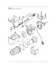
Install combustion chamber<br />
Figure 19<br />
• Use 3 screws (9) M5 x 16 to fix the combustion chamber (8).<br />
Tightening torque M5 x 16 screw.<br />
Lay sensor lead harness and leads of the glow plugs<br />
Figure 20 and 21<br />
• First lay the sensor lead harness (19) in the side cable duct,<br />
then lay the 4 leads of glow plugs 1 (5) and 2 (6) in the cable<br />
duct.<br />
Lay the sensor lead harness (19) and the glow plug leads to<br />
the 14-pin connector (29 - shown in page 33).<br />
• Position the side cover (3) on the middle of the control box /<br />
blower unit (10) and push into the cable duct guide.<br />
Note: It is imperative to keep to the correct laying order for<br />
the sensor lead harness (19) and the glow plug leads.<br />
The glow plug leads may not be laid underneath the<br />
sensor lead harness (19).<br />
The sensor lead harness (19) must be laid in the area<br />
of the fuel pipe as shown in Figure 20.<br />
The side cover (3) is conical at the bottom to simplify<br />
installation.<br />
36