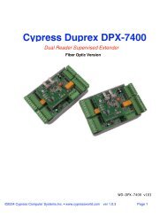
GCS Satellite Hardware Manual - Galaxy Control Systems
GCS Satellite Hardware Manual - Galaxy Control Systems
GCS Satellite Hardware Manual - Galaxy Control Systems

Create successful ePaper yourself
Turn your PDF publications into a flip-book with our unique Google optimized e-Paper software.
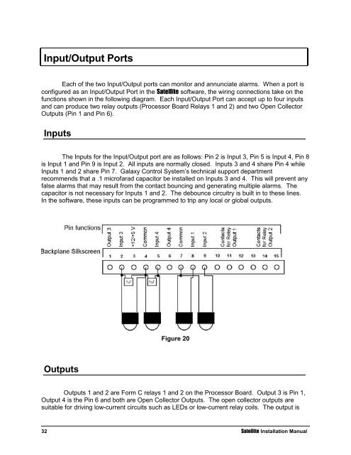
Input/Output Ports<br />
Each of the two Input/Output ports can monitor and annunciate alarms. When a port is<br />
configured as an Input/Output Port in the <strong>Satellite</strong> software, the wiring connections take on the<br />
functions shown in the following diagram. Each Input/Output Port can accept up to four inputs<br />
and can produce two relay outputs (Processor Board Relays 1 and 2) and two Open Collector<br />
Outputs (Pin 1 and Pin 6).<br />
Inputs<br />
The Inputs for the Input/Output port are as follows: Pin 2 is Input 3, Pin 5 is Input 4, Pin 8<br />
is Input 1 and Pin 9 is Input 2. All inputs are normally closed. Inputs 3 and 4 share Pin 4 while<br />
Inputs 1 and 2 share Pin 7. <strong>Galaxy</strong> <strong>Control</strong> System’s technical support department<br />
recommends that a .1 microfarad capacitor be installed on Inputs 3 and 4. This will prevent any<br />
false alarms that may result from the contact bouncing and generating multiple alarms. The<br />
capacitor is not necessary for Inputs 1 and 2. The debounce circuitry is built in to these lines.<br />
In the software, these inputs can be programmed to trip any local or global outputs.<br />
Outputs<br />
Figure 20<br />
Outputs 1 and 2 are Form C relays 1 and 2 on the Processor Board. Output 3 is Pin 1,<br />
Output 4 is the Pin 6 and both are Open Collector Outputs. The open collector outputs are<br />
suitable for driving low-current circuits such as LEDs or low-current relay coils. The output is<br />
32 <strong>Satellite</strong> Installation <strong>Manual</strong>