GCS Satellite Hardware Manual - Galaxy Control Systems
GCS Satellite Hardware Manual - Galaxy Control Systems
GCS Satellite Hardware Manual - Galaxy Control Systems

You also want an ePaper? Increase the reach of your titles
YUMPU automatically turns print PDFs into web optimized ePapers that Google loves.
shield attached to ground at one end only. Keep the conduits as far away as reasonably<br />
possible from all high power and/or high frequency lines. If there are any questions or doubts<br />
concerning the running of wires, please contact <strong>Galaxy</strong> before proceeding. The maximum<br />
distance between controllers is 1000 feet at 9600 Baud.<br />
Line Drivers<br />
<strong>Galaxy</strong> strongly recommends that Line Drivers be used when the network distance<br />
between controllers is greater than 1000 feet, but less than 1.5 miles. Line Drivers are easy to<br />
install and require no hardware changes to the controllers. <strong>Galaxy</strong> can supply Black Box’s<br />
SHMB-2 Short Haul Modem. Other communication technologies such as fiber optics, laser and<br />
radio frequency devices can also be used, however, <strong>Galaxy</strong> <strong>Control</strong> System’s Engineering Staff<br />
should be consulted prior to installing these types of devices.<br />
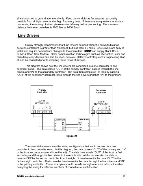
This diagram shows how the line drivers are connected in a one controller to one<br />
controller setup. The data comes “OUT” of the primary controller, passes through the line<br />
drivers and “IN” to the secondary controller. The data then completes the loop by passing<br />
“OUT” of the secondary controller, back through the line drivers and then “IN” to the primary.<br />
Figure 24<br />
The second diagram shows the wiring configuration that would be used in a two<br />
controller to two controller setup. In this diagram, the data passes “OUT” of the primary and “IN”<br />
to the local secondary (second from the left). The data then travels “OUT” of the local or first<br />
secondary and through the line drivers to the remote site. At the remote site, the data is<br />
received “IN” by the second controller from the right. It then transmits the data “OUT” to the<br />
farthest right controller. That controller then transmits the data through the line drivers and “IN”<br />
to the primary controller. These examples should provide enough reference information when<br />
designing the wiring for different numbers of controllers at each location.<br />
<strong>Satellite</strong> Installation <strong>Manual</strong> 35