Expansion modules - Automatech
Expansion modules - Automatech
Expansion modules - Automatech

You also want an ePaper? Increase the reach of your titles
YUMPU automatically turns print PDFs into web optimized ePapers that Google loves.
Basics<br />
Configuration and Wiring<br />
Inputs<br />
Input devices<br />
ESPE<br />
Reset button<br />
When selecting input devices, you<br />
must comply with the technical details<br />
of the input circuits on the PNOZmulti<br />
units. To help you in your selection,<br />
Pilz has performed application tests<br />
with a number of input devices. The<br />
following input devices have passed<br />
the application test:<br />
Light curtains:<br />
– SICK FGS<br />
– SICK C4000<br />
– Honeywell MEYLAN<br />
– CEDES Safe 4<br />
– OMRON F3SN-A<br />
– Fiessler ULVT<br />
– STI Minisafe MS 4600 (from S/N:<br />
AC283791 / BA022933)<br />
– STI Optofence OF 4600<br />
Limit switches:<br />
– Schmersal AZ 16-02<br />
– Guardmaster ferrocode<br />
– Euchner NP1-628AS<br />
– Euchner CES-A-C5E-01 (only<br />
when operating without detection<br />
of shorts across contacts)<br />
– Euchner CES-A-C5E-01 (only<br />
with test pulse wiring)<br />
– Euchner ENG-071990<br />
– Euchner NM11KB<br />
The following may not be used:<br />
Limit switches:<br />
– Euchner CES-A-C5E-01 with<br />
pulse signals<br />
The following is generally valid: Input<br />
devices with mechanical contacts (relays)<br />
can be used in operating modes<br />
with or without detection of shorts<br />
across contacts, provided you comply<br />
with the technical details. It is not always<br />
possible to use input devices<br />
with semiconductor outputs when operating<br />
with detection of shorts across<br />
contacts.<br />
Units with OSSD semiconductor<br />
outputs<br />
Units with OSSD semiconductor outputs<br />
(e.g. self-testing light barriers)<br />
may only be used if the PNOZmulti is<br />
operated without detection of shorts<br />
across contacts.<br />
If the function of an ESPE (e.g. light<br />
barrier) is switched off via an operating<br />
mode selector switch, the supply voltage<br />
to the ESPE must be switched off<br />
at the same time.<br />
Operating modes<br />
The following operating modes are<br />
available, depending on the selected<br />
safety function:<br />
Single-channel operation: Input<br />
wiring in accordance with EN<br />
60204, no redundancy in the input<br />
circuit; earth faults in the input circuit<br />
are detected.<br />
Dual-channel operation: Redundant<br />
input circuit; earth faults in the<br />
input circuit are detected, with or<br />
without detection of shorts between<br />
the input contacts.<br />
Triple-channel operation: Redundant<br />
input circuit; earth faults in the<br />
input circuit are detected, with or<br />
without detection of shorts between<br />
the input contacts.<br />
Automatic reset: Unit is active as<br />
soon as the input circuit is closed.<br />
Manual reset: The unit is not active<br />
until the reset button has been operated.<br />
Monitored reset: Unit is not active<br />
until the reset button has been operated<br />
and then released. This eliminates<br />
the possibility of the reset<br />
button being overridden, triggering<br />
automatic activation.<br />
Detection of shorts between contacts<br />
in the input circuit: Enabled by<br />
pulsing the input circuits. This operating<br />
mode is automatically detected<br />
on start-up.<br />
Detection of shorts between contacts<br />
in the reset circuit:<br />
Only on E-STOP, safety gate and<br />
light curtain<br />
Start-up test: The unit checks<br />
whether safety gates that are<br />
closed are opened and then closed<br />
again when supply voltage is applied.<br />
Increase in the number of safety<br />
contacts available by connecting a<br />
contact block (e.g. PZE 9P) or external<br />
contactors.<br />
A reset button triggers an enable for a<br />
safety device when all the corresponding<br />
safety switches (e.g. E-STOP) are<br />
closed. This prevents a machine starting<br />
up automatically after the supply<br />
has been interrupted or after a safety<br />
device has closed, for example.<br />
Reset modes<br />
When configuring inputs for E-STOPs,<br />
safety gates or light guards in the<br />
PNOZmulti Configurator, it is possible<br />
to define the reset mode:<br />
Automatic reset<br />
Manual reset<br />
Monitored reset<br />
For a manual and monitored reset, the<br />
reset button can also be configured as<br />
a standard input.<br />
Automatic reset<br />
With an automatic reset, the output on<br />
the function element goes to “1” when<br />
the safety switches on the input circuit<br />
are closed.<br />
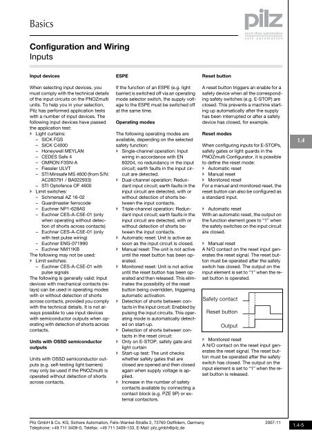
Manual reset<br />
A N/O contact on the reset input generates<br />
the reset signal. The reset button<br />
must be operated after the safety<br />
switch has closed. The output on the<br />
input element is set to “1” when the reset<br />
button is operated.<br />
Safety contact<br />
Reset button<br />
Output<br />
Monitored reset<br />
A N/O contact on the reset input generates<br />
the reset signal. The reset button<br />
must be operated after the safety<br />
switch has closed. The output on the<br />
input element is set to “1” when the reset<br />
button is released.<br />
1.4<br />
Pilz GmbH & Co. KG, Sichere Automation, Felix-Wankel-Straße 2, 73760 Ostfildern, Germany<br />
Telephone: +49 711 3409-0, Telefax: +49 711 3409-133, E-Mail: pilz.gmbh@pilz.de<br />
2007-11<br />
1.4-5