Expansion modules - Automatech
Expansion modules - Automatech
Expansion modules - Automatech

Create successful ePaper yourself
Turn your PDF publications into a flip-book with our unique Google optimized e-Paper software.
Products<br />
<strong>Expansion</strong> <strong>modules</strong><br />
PNOZ ma1p<br />
Wiring<br />
Please note the following when preparing<br />
for commissioning:<br />
The wiring is defined in the circuit<br />
diagram of the PNOZmulti Configurator.<br />
The power supply that feeds the expansion<br />
module and the input device<br />
must meet the regulations for<br />
extra low voltages with safe separation<br />
(SELV, PELV).<br />
6 connection terminals are available<br />
for each of the supply connections<br />
24 V and 0 V. This means that the<br />
supply voltage can be looped<br />
through several connections and<br />
the input device can be supplied.<br />
Use shielded, twisted pair cable for<br />
the connections on the input current<br />
circuits.<br />
Separate the supply voltage cable<br />
from the analogue input current<br />
lines.<br />
If the analogue input module is<br />
used to measure current, the voltage<br />
inputs must be short-circuited.<br />
For transducers located outside the<br />
control cabinet: Where the cable<br />
enters the control cabinet, the cable<br />
shield must be connected to the<br />
earth potential over a wide surface<br />
area and with low impedance (connect<br />
in star).<br />
Use copper wiring that can withstand<br />
temperatures of 60/75 °C.<br />
The torque setting of the screws on<br />
the connection terminals is specified<br />
in the "Technical details" section.<br />
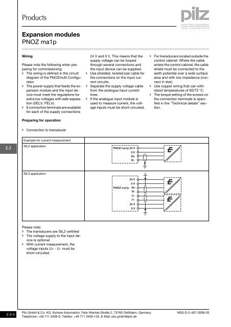
Preparing for operation<br />
Connection to transducer<br />
Example for current measurement<br />
2.3<br />
SIL2 application<br />
SIL3 application<br />
24 V<br />
PNOZ ma1p 24 V<br />
0 V<br />
I0+<br />
I0-<br />
0 V<br />
PNOZ ma1p I0+<br />
I0-<br />
I1-<br />
I1-<br />
24 V<br />
0 V<br />
Please note:<br />
The transducers are SIL2 certified<br />
The voltage supply to the input device<br />
is optional<br />
With current measurement, the<br />
voltage inputs U+ - U- must be<br />
short-circuited.<br />
2.3-4<br />
Pilz GmbH & Co. KG, Sichere Automation, Felix-Wankel-Straße 2, 73760 Ostfildern, Germany<br />
Telephone: +49 711 3409-0, Telefax: +49 711 3409-133, E-Mail: pilz.gmbh@pilz.de<br />
NSG-D-2-407-2008-03