AVR 240 OM - Harman Kardon
AVR 240 OM - Harman Kardon
AVR 240 OM - Harman Kardon

You also want an ePaper? Increase the reach of your titles
YUMPU automatically turns print PDFs into web optimized ePapers that Google loves.
<strong>AVR</strong><strong>240</strong><br />
harman/kardon<br />
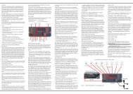
INSTALLATION AND CONNECTIONS<br />
or any other video source to the Video 2<br />
Audio/Video and S-Video Input Jacks .<br />
Although any video device may be connected to<br />
these jacks, we recommend connecting your cable<br />
TV converter or satellite receiver so that you may<br />
take advantage of the fact that the remote control is<br />
preprogrammed with the product codes of these<br />
device types for the Video 2 device.<br />
3. Connect the analog audio and video outputs of<br />
a television or other video device to the Video 3<br />
Audio and Video Input Jacks on the rear<br />
panel. Although any video or audio device may be<br />
connected to these jacks, we recommend connecting<br />
your television so that you may take advantage<br />
of the fact that the remote control is preprogrammed<br />
with TV product codes for the Video 3 device.<br />
Important: If you are only using the television as a<br />
display device (i.e., if you receive your television<br />
programs through a cable box or satellite receiver),<br />
do not connect the television’s outputs to the Video<br />
3 Audio and Video Input Jacks , or to any<br />
other inputs on the <strong>AVR</strong> <strong>240</strong>.<br />
4. Connect the analog audio and video outputs of a<br />
DVD or laser disc player to the DVD Audio/Video<br />
and S-Video Inputs d.<br />
5. Connect the digital audio outputs of a DVD player,<br />
satellite receiver, cable box or HDTV converter to<br />
the appropriate Optical or Coaxial Digital Inputs<br />
bg*(. Remember that the DVD source<br />
defaults to the Coaxial 1 Digital Input ·, and<br />
the Video 2/Cable/Sat source defaults to the<br />
Optical 1 Digital Audio Input g. All other<br />
sources default to their analog inputs, although<br />
any source may be assigned to any digital audio<br />
input on the receiver.<br />
6. Connect the Video and/or S-Video Monitor<br />
Output c jacks on the receiver to the composite<br />
or S-video input of your television monitor or<br />
video projector.<br />
7. If both your video display monitor and at least one<br />
video source device, such as a DVD player or<br />
HDTV set-top box, is equipped with component<br />
video capability, then you may connect the component<br />
video outputs of the device to one of the two<br />
Component Video Inputs ›fi.<br />
It is recommended that you connect a DVD player or<br />
a digital recorder to the Component Video 1 Inputs<br />
›, as this input is assigned to the DVD, CD, Tuner<br />
and Tape sources by default. Thus, whenever any of<br />
these sources is selected, you may view the component<br />
video output of the device connected to the<br />
Component Video 1 Inputs ›, enabling you<br />
to view and listen to different sources.<br />
Similarly, it is recommended that you connect any<br />
other audio/video device, such as a DVD-Audio or<br />
SACD player or HDTV set-top box, to the Video 1,<br />
Video 2 or Video 3 sources, or the 6-/8-channel<br />
direct inputs, as the Component Video 2 Inputs fi<br />
are assigned to the Video 1, Video 2, Video 3 and<br />
6-/8-channel source audio inputs by default.<br />
However, you may connect any component video<br />
source to either set of component video inputs, as<br />
they are assignable to any source. You will still need to<br />
connect either the analog or digital audio outputs, or<br />
the 6-/8-channel audio outputs, of your component<br />
video device to the analog audio inputs corresponding<br />
to the source (such as DVD or Video 2 for a cable<br />
converter box), or to any of the Optical or Coaxial<br />
Digital Audio Inputs bg*(.<br />
8. If the component video inputs are used, connect<br />
the Component Video Monitor Outputs ‹ to<br />
the component video inputs of your TV, projector<br />
or display device.<br />
9. If you have a camcorder, video game or other<br />
audio/video device that is connected to the <strong>AVR</strong> on<br />
a temporary rather than permanent basis, connect<br />
the audio, video and digital audio outputs of that<br />
device to the Video 4 Inputs *(ÓÔ on the<br />
front panel. A device connected here is selected as<br />
the Video 4 input, and the digital inputs must be<br />
assigned to the Video 4 input. (See page 20 for<br />
more information on input configuration.)<br />
VIDEO CONNECTION NOTES:<br />
• When the component video jacks are used, the onscreen<br />
menus are not visible and you must switch<br />
to the standard composite or S-video input on your<br />
TV to view them.<br />
• The <strong>AVR</strong> <strong>240</strong> will accept either standard composite,<br />
S-video or Y/Pr/Pb component video signals. However,<br />
it will not convert any of these signals to a<br />
different format.<br />
• When connecting a video source to the <strong>AVR</strong> <strong>240</strong>,<br />
you may use either composite, component or S-<br />
video, but only one type of video may be connected<br />
for each device.<br />
• When more than one video format is used, it is<br />
necessary to make a separate connection from<br />
the <strong>AVR</strong> to your video display for each format.<br />
For example, if both composite and component<br />
sources are connected to the <strong>AVR</strong> <strong>240</strong>, both the<br />
Composite and Component Video Monitor<br />
Outputs ‹ must be connected to the appropriate<br />
inputs on your video display.<br />
System and Power Connections<br />
The <strong>AVR</strong> <strong>240</strong> is designed for flexible use with external<br />
control components.<br />
Main Room Remote Control Extension<br />
If the receiver is placed behind a solid or smoked<br />
glass cabinet door, the obstruction may prevent the<br />
remote sensor from receiving commands. In this<br />
event, an optional remote sensor may be used.<br />
Connect the output of the remote sensor to the<br />
Remote IR Input ∞ jack.<br />
If other components are also prevented from receiving<br />
remote commands, only one sensor is needed. Simply<br />
use this unit’s sensor or a remote eye by running a<br />
connection from the Remote IR Output § jack to<br />
the Remote IR Input jack on <strong>Harman</strong> <strong>Kardon</strong> or other<br />
compatible equipment.<br />
AC Power Connections<br />
This unit is equipped with two accessory AC outlets.<br />
They may be used to power accessory devices, but<br />
they should not be used with high-current-draw equipment<br />
such as power amplifiers. The total power draw<br />
to each outlet may not exceed 100 watts.<br />
The Switched AC Accessory Outlet ‡ will receive<br />
power only when the unit is on. This is recommended<br />
for devices that have no power switch or a mechanical<br />
power switch that may be left in the “ON” position.<br />
NOTE: Many audio and video products go into a<br />
Standby mode when they are used with switched outlets,<br />
and cannot be fully turned on using the outlet<br />
alone without a remote control command.<br />
The Unswitched AC Accessory Outlet ° will<br />
receive power as long as the unit is plugged into a<br />
powered AC outlet.<br />
Once the AC Power Cord fl is connected, you are<br />
almost ready to enjoy the <strong>AVR</strong> <strong>240</strong>’s incredible power<br />
and fidelity!<br />
16 INSTALLATION AND CONNECTIONS<br />
17