AVR 240 OM - Harman Kardon
AVR 240 OM - Harman Kardon
AVR 240 OM - Harman Kardon

Create successful ePaper yourself
Turn your PDF publications into a flip-book with our unique Google optimized e-Paper software.
<strong>AVR</strong><strong>240</strong><br />
FRONT-PANEL CONTROLS<br />
harman/kardon<br />
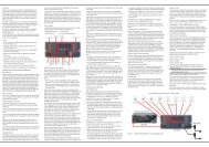
6 Speaker Selector: Press this button to begin<br />
the process of configuring the unit to match the type<br />
of speakers used in your listening room. (See pages<br />
26–28 for more information on speaker setup and<br />
configuration.)<br />
7 Surround Mode Group Selector: Press this button<br />
to select the top-level group of surround modes.<br />
Each press of the button will select the current or last<br />
used mode in each of the surround mode groups<br />
(e.g., Dolby, DTS, DTS Neo:6, Logic 7, DSP, Stereo).<br />
When the button is pressed so that the name of the<br />
surround mode group appears in the on-screen display<br />
and in the Lower Display Line ı, press the<br />
Surround Mode Selector 8 to cycle through the<br />
individual modes available. For example, press this<br />
button to select Dolby modes, and then press the<br />
Surround Mode Selector 8 to choose from the<br />
various Dolby mode options.<br />
8 Surround Mode Selector: Press this button<br />
to select from among the available surround mode<br />
options for the mode group selected. The specific<br />
modes will vary based on the number of speakers<br />
available, the mode group and if the input source is<br />
digital or analog. For example, press the Surround<br />
Mode Group Selector 7 to select a main mode<br />
grouping such as Dolby or Logic 7, and then press<br />
this button to see the specific mode choices available.<br />
Note that the digital surround modes, such as Dolby<br />
Digital and DTS, may not be accessed unless that type<br />
of source signal is present, such as when a DVD movie<br />
or television signal programmed in Dolby Digital or DTS<br />
surround sound is playing. For more information on surround<br />
mode selection, see pages 23 and 32.<br />
9 Tuning Selector: Press the left side of the button<br />
to tune lower-frequency stations and the right side of<br />
the button to tune higher-frequency stations. When the<br />
tuner is in the Manual mode, each tap will increase or<br />
decrease the frequency by one increment. When the<br />
tuner receives a strong enough signal for adequate<br />
reception, MANUAL TUNED will appear in the<br />
on-screen display and the Lower Display Line ı.<br />
When the tuner is the Auto mode, press the button<br />
once, and the tuner will scan for a station with acceptable<br />
signal strength. When the next station with a<br />
strong signal is tuned the scan will stop and the<br />
on-screen display and Lower Display Line ı<br />
will indicate AUTO TUNED. When an FM<br />
Stereo station is tuned, the display will read<br />
AUTO ST TUNED.<br />
To switch back and forth between the Auto and<br />
Manual tuning modes, press the Tuner Mode<br />
Selector &.<br />
) ‹/› Buttons: When configuring the <strong>AVR</strong> <strong>240</strong>’s<br />
settings, use these buttons to select from the available<br />
choices.<br />
! Tuner Band Selector: Press this button to turn<br />
the <strong>AVR</strong> on and to select the Tuner as the input. Press<br />
it again to switch between the AM and FM frequency<br />
bands. (See page 37 for more information on the tuner.)<br />
@ Set Button: When making choices during the<br />
setup and configuration process, press this button<br />
to enter the desired setting into the <strong>AVR</strong> <strong>240</strong>’s memory.<br />
# Digital Input Selector: Press this button to<br />
select one of the digital audio inputs or the analog<br />
audio input for any source. (See pages 32–37 for<br />
more information on digital audio.)<br />
$ Preset Stations Selector: Press this button to<br />
scroll up or down through the list of stations that have<br />
been entered into the preset memory. (See page 37<br />
for more information on tuner presets.)<br />
% Delay Adjust Selector: Press this button to<br />
begin the steps required to enter delay settings. (See<br />
pages 28–29 for more information on delay times.)<br />
^ Input Source Selector: Press this button to<br />
change the input by scrolling up or down through the<br />
list of Input Indicators Ú.<br />
& Tuner Mode Selector: Press this button to select<br />
Auto or Manual tuning. When the button is pressed so<br />
that the AUTO appears in the Lower Display Line<br />
ı, the tuner will search for the next station with an<br />
acceptable signal when the Tuning Selector 9u<br />
is pressed. When the button is pressed so that<br />
MANUAL appears in the Lower Display Line ı,<br />
each press of the Tuning Selector 9u will<br />
increase the frequency. This button may also be used to<br />
switch between Stereo and Mono modes for FM radio<br />
reception. When weak reception is encountered, press<br />
the button so that MANUAL appears in the Lower<br />
Display Line ı and on the on-screen display to<br />
switch to Mono reception. Press it again to switch back<br />
to Stereo mode. (See page 37 for more information on<br />
using the tuner.)<br />
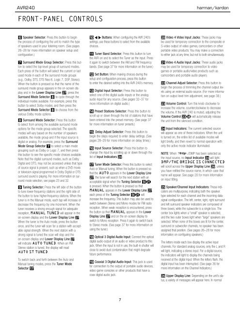
* Optical 3 Digital Audio Input: Connect the optical<br />
digital audio output of an audio or video product to this<br />
jack. When the input is not in use, the built-in shutter will<br />
close to avoid dust contamination that might degrade<br />
future performance.<br />
( Coaxial 3 Digital Audio Input: This jack is used<br />
for connection to the output of portable audio devices,<br />
video game consoles or other products that have a<br />
coax digital audio jack.<br />
Ó Video 4 Video Input Jacks: These jacks may<br />
be used for temporary connection to the composite or<br />
S-video output of video games, camcorders or other<br />
portable video products. You may make a connection<br />
to either jack at any time, but not to both simultaneously.<br />
Ô Video 4 Audio Input Jacks: These audio jacks<br />
may be used for temporary connection to video<br />
games or portable audio/video products such as<br />
camcorders and portable audio players.<br />
apple Channel Adjust Selector: Press this button to<br />
begin the process of trimming the channel output levels<br />
using an external audio source. (For more information<br />
on output level trim adjustment, see page 38.)<br />
Ò Volume Control: Turn this knob clockwise to<br />
increase the volume, counterclockwise to decrease<br />
the volume. If the <strong>AVR</strong> <strong>240</strong> is muted, adjusting the<br />
Volume Control Ò will automatically release<br />
the unit from the silenced condition.<br />
Ú Input Indicators: The current selected source<br />
will appear as one of these indicators. When the unit<br />
is turned on, the entire list of available modes will<br />
light briefly, and then revert to normal operation with<br />
only the active mode indicator illuminated.<br />
The<br />
BridgeTM<br />
NOTE: When /DMP has been selected as<br />
the input source, no Input Indicator N will light.<br />
DMP/THE BRIDGE IS CONNECTED<br />
will scroll across the Upper Display Line P, unless<br />
you have retitled the source name, in which case that<br />
name will appear. See page 20 for more information<br />
on input titling.<br />
Û Speaker/Channel Input Indicators: These indicators<br />
are multipurpose, indicating both the speaker<br />
type selected for each channel and the incoming datasignal<br />
configuration. The left, center, right, right surround<br />
and left surround speaker indicators are composed of<br />
three boxes, while the subwoofer is a single box. The<br />
center box lights when a “small” speaker is selected,<br />
and the two outer boxes light when “large” speakers are<br />
selected. When none of the boxes are lit for the center,<br />
surround or subwoofer channels, no speaker has been<br />
assigned that position. (See pages 26–28 for more<br />
information on configuring speakers.)<br />
The letters inside each box display the active input<br />
channels. For standard analog sources, only the L and R<br />
will light, indicating a stereo input. For a digital source,<br />
the indicators will light to display the channels being<br />
received at the digital input. When the letters flash, the<br />
digital input has been interrupted. (See page 36 for<br />
more information on the Channel Indicators.)<br />
Ù Upper Display Line: Depending on the unit’s status,<br />
a variety of messages will appear here. In normal<br />
6 FRONT-PANEL CONTROLS<br />
7