

Demystifying Auto-Zero Amplifiers—Part 1 - Analog Devices
Demystifying Auto-Zero Amplifiers—Part 1 - Analog Devices
Demystifying Auto-Zero Amplifiers—Part 1 - Analog Devices

Create successful ePaper yourself
Turn your PDF publications into a flip-book with our unique Google optimized e-Paper software.
versatile machine will use both techniques to handle differing<br />
circumstances. ACPI outlines the cooling techniques in terms of<br />
two different modes: performance mode and silent mode. The two<br />
modes are compared in Figures 1 and 2.<br />
100C<br />
90C<br />
80C<br />
70C<br />
TEMP<br />
*<br />
*<br />
*<br />
*<br />
HIGH LIMIT<br />
90<br />
85<br />
80<br />
75<br />
60<br />
55<br />
50<br />
45<br />
40<br />
35<br />
30<br />
25<br />
20<br />
15<br />
10<br />
5<br />
_CRT<br />
_PSV<br />
_ACx<br />
POLICY<br />
SCI EVENT<br />
90<br />
85<br />
80<br />
75<br />
60<br />
55<br />
50<br />
45<br />
40<br />
35<br />
30<br />
25<br />
20<br />
15<br />
10<br />
5<br />
_CRT<br />
_ACx<br />
_PSV<br />
POLICY<br />
SCI EVENT<br />
1 2<br />
Figure 1. Performance preferred. Active mode (_ACx, fan on)<br />
is entered at 50°, passive mode (_PSV, throttle back) is entered<br />
at 60°. Shutdown occurs at the critical temperature<br />
(_CRT) 90°. Fan speed may increase at levels above ACx.<br />
Figure 2. Silence and battery economy preferred. Passive mode<br />
is first entered at 45°, and fan is not turned on until 60°.<br />
Figures 1 and 2 are examples of temperature scales that illustrate<br />
the respective trade-offs between performance, fan acoustic noise,<br />
and power consumption/dissipation. In order for a systemmanagement<br />
device to be ACPI-compliant, it should be capable<br />
of signaling limit crossings at, say, 5°C intervals, or SCI (systemcontrol<br />
interrupt) events, that a new out-of-limit temperature<br />
increment has occurred. These events provide a mechanism by<br />
which the OS can track the system temperature and make informed<br />
decisions as to whether to throttle the CPU clock, increase/decrease<br />
the speed of the cooling fan, or take more drastic action. Once the<br />
temperature exceeds the _CRT (critical temperature) policy setting,<br />
the system will be shut down as a fail-safe to protect the CPU. The<br />
other two policy settings shown in Figures 1 and 2 are _PSV<br />
(passive cooling, or CPU clock throttling) and _ACx (active<br />
cooling, when the fan switches on).<br />
In Figure 1 (performance mode), the cooling fan is switched on at<br />
50°C. Should the temperature continue to rise beyond 60°C, clock<br />
throttling is initiated. This behavior will maximize system<br />
performance, since the system is only being slowed down at a higher<br />
temperature. In Figure 2 (silent mode), the CPU clock is first<br />
throttled at 45°C. If the temperature continues to rise, a cooling<br />
fan may be switched on at 60°C. This reduced-performance mode<br />
will also tend to increase battery life, since throttling back the<br />
clock reduces power consumption.<br />
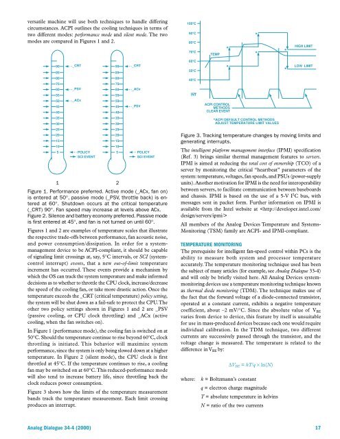
Figure 3 shows how the limits of the temperature measurement<br />
bands track the temperature measurement. Each limit crossing<br />
produces an interrupt.<br />
60C<br />
50C<br />
40C<br />
INT<br />
*<br />
ACPI CONTROL<br />
METHODS<br />
CLEAR EVENT<br />
*ACPI DEFAULT CONTROL METHODS<br />
ADJUST TEMPERATURE LIMIT VALUES<br />
*<br />
LOW LIMIT<br />
Figure 3. Tracking temperature changes by moving limits and<br />
generating interrupts.<br />
The intelligent platform management interface (IPMI) specification<br />
(Ref. 3) brings similar thermal management features to servers.<br />
IPMI is aimed at reducing the total cost of ownership (TCO) of a<br />
server by monitoring the critical “heartbeat” parameters of the<br />
system: temperature, voltages, fan speeds, and PSUs (power-supply<br />
units). Another motivation for IPMI is the need for interoperability<br />
between servers, to facilitate communication between baseboards<br />
and chassis. IPMI is based on the use of a 5-V I 2 C bus, with<br />
messages sent in packet form. Further information on IPMI is<br />
available from the Intel website at <br />
All members of the <strong>Analog</strong> <strong>Devices</strong> Temperature and Systems-<br />
Monitoring (TSM) family are ACPI- and IPMI-compliant.<br />
TEMPERATURE MONITORING<br />
The prerequisite for intelligent fan-speed control within PCs is the<br />
ability to measure both system and processor temperature<br />
accurately. The temperature monitoring technique used has been<br />
the subject of many articles (for example, see <strong>Analog</strong> Dialogue 33-4)<br />
and will only be briefly visited here. All <strong>Analog</strong> <strong>Devices</strong> systemmonitoring<br />
devices use a temperature monitoring technique known<br />
as thermal diode monitoring (TDM). The technique makes use of<br />
the fact that the forward voltage of a diode-connected transistor,<br />
operated at a constant current, exhibits a negative temperature<br />
coefficient, about –2 mV/°C. Since the absolute value of V BE<br />
varies from device to device, this feature by itself is unsuitable<br />
for use in mass-produced devices because each one would require<br />
individual calibration. In the TDM technique, two different<br />
currents are successively passed through the transistor, and the<br />
voltage change is measured. The temperature is related to the<br />
difference in V BE by:<br />
where:<br />
∆V BE = kT/q × ln(N)<br />
k = Boltzmann’s constant<br />
q = electron charge magnitude<br />
T = absolute temperature in kelvins<br />
N = ratio of the two currents<br />
<strong>Analog</strong> Dialogue 34-4 (2000) 17


