

Demystifying Auto-Zero Amplifiers—Part 1 - Analog Devices
Demystifying Auto-Zero Amplifiers—Part 1 - Analog Devices
Demystifying Auto-Zero Amplifiers—Part 1 - Analog Devices

Create successful ePaper yourself
Turn your PDF publications into a flip-book with our unique Google optimized e-Paper software.
adjustable filter cutoff, output rate, and settling time processes<br />
the modulator output. There are two buffered differential<br />
programmable-gain analog inputs, as well as a differential reference<br />
input. It accepts four unipolar and bipolar analog input ranges<br />
from 10 mV to 80 mV full-scale.<br />
The peak-to-peak resolution achievable directly is 1-in-230,000<br />
counts. An on-chip 6-bit DAC allows compensation for tare voltage<br />
in weigh-scale applications. The device’s serial interface can be<br />
configured for 3-wire operation and is compatible with<br />
microcontrollers and digital signal-processors. The AD7730<br />
contains self-calibration and system calibration options, and<br />
features an offset drift of less than 5 nV/°C and a gain drift of less<br />
than 2 ppm/°C. With this level of drift performance, calibration in<br />
the field is usually unnecessary.<br />
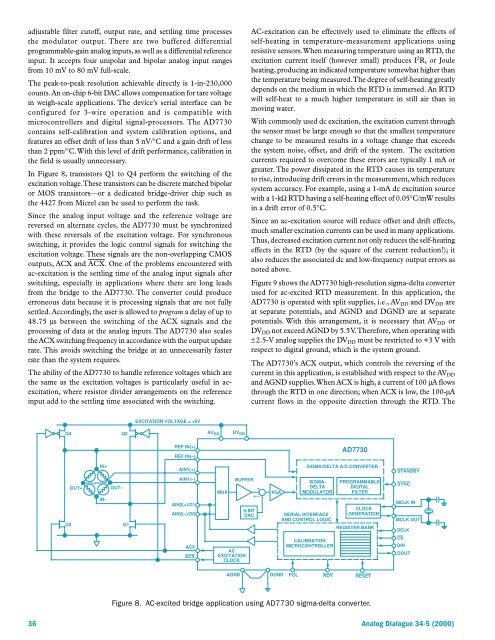
In Figure 8, transistors Q1 to Q4 perform the switching of the<br />
excitation voltage. These transistors can be discrete matched bipolar<br />
or MOS transistors—or a dedicated bridge-driver chip such as<br />
the 4427 from Micrel can be used to perform the task.<br />
Since the analog input voltage and the reference voltage are<br />
reversed on alternate cycles, the AD7730 must be synchronized<br />
with these reversals of the excitation voltage. For synchronous<br />
switching, it provides the logic control signals for switching the<br />
excitation voltage. These signals are the non-overlapping CMOS<br />
outputs, ACX and ACX. One of the problems encountered with<br />
ac-excitation is the settling time of the analog input signals after<br />
switching, especially in applications where there are long leads<br />
from the bridge to the AD7730. The converter could produce<br />
erroneous data because it is processing signals that are not fully<br />
settled. Accordingly, the user is allowed to program a delay of up to<br />
48.75 µs between the switching of the ACX signals and the<br />
processing of data at the analog inputs. The AD7730 also scales<br />
the ACX switching frequency in accordance with the output update<br />
rate. This avoids switching the bridge at an unnecessarily faster<br />
rate than the system requires.<br />
The ability of the AD7730 to handle reference voltages which are<br />
the same as the excitation voltages is particularly useful in acexcitation,<br />
where resistor divider arrangements on the reference<br />
input add to the settling time associated with the switching.<br />
AC-excitation can be effectively used to eliminate the effects of<br />
self-heating in temperature-measurement applications using<br />
resistive sensors. When measuring temperature using an RTD, the<br />
excitation current itself (however small) produces I 2 R, or Joule<br />
heating, producing an indicated temperature somewhat higher than<br />
the temperature being measured. The degree of self-heating greatly<br />
depends on the medium in which the RTD is immersed. An RTD<br />
will self-heat to a much higher temperature in still air than in<br />
moving water.<br />
With commonly used dc excitation, the excitation current through<br />
the sensor must be large enough so that the smallest temperature<br />
change to be measured results in a voltage change that exceeds<br />
the system noise, offset, and drift of the system. The excitation<br />
currents required to overcome these errors are typically 1 mA or<br />
greater. The power dissipated in the RTD causes its temperature<br />
to rise, introducing drift errors in the measurement, which reduces<br />
system accuracy. For example, using a 1-mA dc excitation source<br />
with a 1-kΩ RTD having a self-heating effect of 0.05°C/mW results<br />
in a drift error of 0.5°C.<br />
Since an ac-excitation source will reduce offset and drift effects,<br />
much smaller excitation currents can be used in many applications.<br />
Thus, decreased excitation current not only reduces the self-heating<br />
effects in the RTD (by the square of the current reduction!); it<br />
also reduces the associated dc and low-frequency output errors as<br />
noted above.<br />
Figure 9 shows the AD7730 high-resolution sigma-delta converter<br />
used for ac-excited RTD measurement. In this application, the<br />
AD7730 is operated with split supplies, i.e., AV DD and DV DD are<br />
at separate potentials, and AGND and DGND are at separate<br />
potentials. With this arrangement, it is necessary that AV DD or<br />
DV DD not exceed AGND by 5.5 V. Therefore, when operating with<br />
± 2.5-V analog supplies the DV DD must be restricted to +3 V with<br />
respect to digital ground, which is the system ground.<br />
The AD7730’s ACX output, which controls the reversing of the<br />
current in this application, is established with respect to the AV DD<br />
and AGND supplies. When ACX is high, a current of 100 µA flows<br />
through the RTD in one direction; when ACX is low, the 100-µA<br />
current flows in the opposite direction through the RTD. The<br />
EXCITATION VOLTAGE = +5V<br />
Q4<br />
Q2<br />
REF IN(+)<br />
REF IN(–)<br />
AV DD DV DD<br />
AD7730<br />
IN+<br />
SIGMA-DELTA A/D CONVERTER<br />
STANDBY<br />
Q3<br />
OUT+<br />
IN–<br />
OUT–<br />
Q1<br />
AIN1(+)<br />
AIN1(–)<br />
AIN2(+)/D1<br />
AIN2(–)/D0<br />
MUX<br />
BUFFER<br />
6-BIT<br />
DAC<br />
+<br />
+/–<br />
PGA<br />
SIGMA-<br />
DELTA<br />
MODULATOR<br />
SERIAL INTERFACE<br />
AND CONTROL LOGIC<br />
PROGRAMMABLE<br />
DIGITAL<br />
FILTER<br />
CLOCK<br />
GENERATION<br />
REGISTER BANK<br />
SYNC<br />
MCLK IN<br />
MCLK OUT<br />
SCLK<br />
CS<br />
DIN<br />
DOUT<br />
ACX<br />
ACX<br />
AC<br />
EXCITATION<br />
CLOCK<br />
CALIBRATION<br />
MICROCONTROLLER<br />
AGND<br />
DGND<br />
POL<br />
RDY<br />
RESET<br />
Figure 8. AC-excited bridge application using AD7730 sigma-delta converter.<br />
36 <strong>Analog</strong> Dialogue 34-5 (2000)


