

Demystifying Auto-Zero Amplifiers—Part 1 - Analog Devices
Demystifying Auto-Zero Amplifiers—Part 1 - Analog Devices
Demystifying Auto-Zero Amplifiers—Part 1 - Analog Devices

Create successful ePaper yourself
Turn your PDF publications into a flip-book with our unique Google optimized e-Paper software.
on pictures with significant high frequency content; that is, pictures<br />
that contain lots of detail and color. The digital noise reduction<br />
(DNR) used on the ADV719x effectively reduces noise in the<br />
picture, and also has the ability to reduce noise that results from<br />
the MPEG compression. MPEG compression splits the video data<br />
contained in one frame into compressed blocks of 8 × 8 pixels.<br />
Several of these blocks make up a field. The border areas of these<br />
blocks cause noise to be visible on the TV picture, which makes it<br />
generally less sharp. This type of signal degradation is typical of<br />
MPEG compression. In the ADV719x family of video encoders,<br />
the amount of noise reduction applied to the transition areas is<br />
programmable.<br />
Video noise characteristically combines high frequencies and low<br />
amplitudes. The ADV719x makes use of this fact by analyzing the<br />
incoming signal for its high-frequency, low-amplitude content. This<br />
noise signal is then subtracted from the original signal, resulting<br />
in improved picture quality. Depending upon the noise<br />
requirements, the user can program a threshold value that<br />
determines the amount of noise attenuation applied.<br />
Additionally, programming allows high-frequency signals to be<br />
enhanced. When received, high-frequency signals with high<br />
amplitudes are assumed to be valid data. Applying a programmable<br />
gain to these signals and adding them to the original signal results<br />
in an improvement in picture sharpness.<br />
Figure 3 shows a simulation of an input signal (light trace) and<br />
the resulting output signal (heavy trace) when digital noise<br />
reduction is applied.<br />
BINARY CODE<br />
240<br />
220<br />
200<br />
180<br />
160<br />
140<br />
120<br />
100<br />
80<br />
60<br />
0 20 40 60 80 100 120 140 160<br />
SAMPLES<br />
Figure 3. Effect of digital noise reduction. Heavy trace is<br />
output waveform.<br />
Gamma Correction: Gamma is the exponent applied to a signal<br />
voltage in an approximation of the nonlinear transfer function of a<br />
display device (e.g., a cathode-ray tube screen). Gamma = 1.0<br />
would produce a perfectly linear plot, i.e., the output as a linear<br />
function of the input. In CRTs the intensity of light produced on<br />
the screen of a CRT is a nonlinear function of the voltage applied<br />
at the input, with a typical gamma value of 2.3 to 2.6.<br />
Gamma correction, a process of compensating for this nonlinearity,<br />
is necessary for reproducing good color with the correct intensity<br />
in order to meet standards for picture appearance on a given screen.<br />
The nonlinearity of the CRT should also be considered if an image<br />
is to be coded in such a way as to make maximum perceptual use<br />
of a limited number of bits per pixel and to minimize the visibility<br />
of noise. If uncompensated, the nonlinearity would create errors<br />
known as contouring or banding. These are visible on simple<br />
pictures having large areas of smoothly varying shades. This is<br />
effectively the same as the visible distortion caused by quantization<br />
error introduced at low levels of modulation.<br />
Display devices, such as liquid crystal displays (LCDs) and CRTs,<br />
have differing nonlinearity characteristics. The ADV719x allows<br />
the user to program gamma values so that appropriate<br />
compensation curves can be applied to the incoming signal.<br />
Gamma correction in the display device is especially useful in cases<br />
where the video source doesn’t provide a gamma-corrected signal.<br />
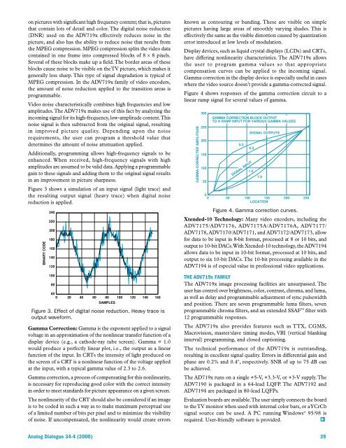
Figure 4 shows responses of the gamma correction circuit to a<br />
linear ramp signal for several values of gamma.<br />
GAMMA-CORRECTED AMPLITUDE<br />
300<br />
250<br />
200<br />
150<br />
100<br />
50<br />
0<br />
GAMMA CORRECTION BLOCK OUTPUT<br />
TO A RAMP INPUT FOR VARIOUS GAMMA VALUES<br />
0.3<br />
SIGNAL INPUT<br />
SIGNAL OUTPUTS<br />
0.5<br />
1.5<br />
1.8<br />
0 50 100 150 200 250<br />
LOCATION<br />
Figure 4. Gamma correction curves.<br />
Xtended-10 Technology: Many video encoders, including the<br />
ADV7175/ADV7176, ADV7175A/ADV7176A, ADV7177/<br />
ADV7178, ADV7170/ADV7171, and ADV7172/ADV7173, allow<br />
for data to be input in 8-bit format, processed at 8 or 10 bits, and<br />
output to 10-bit DACs. With Xtended-10 technology, the ADV7194<br />
allows data to be input in 10-bit format, processed at 10 bits, and<br />
output to six 10-bit DACs. The 10-bit processing available in the<br />
ADV7194 is of especial value in professional video applications.<br />
THE ADV719x FAMILY<br />
The ADV719x image processing facilities are unsurpassed. The<br />
user has control over brightness, color, contrast, chroma, and luma,<br />
as well as delay and programmable adjustment of sync pulsewidth<br />
and position. There are seven programmable luma filters, seven<br />
programmable chroma filters, and an extended SSAF filter with<br />
12 programmable responses.<br />
The ADV719x also provides features such as TTX, CGMS,<br />
Macrovision, master/slave timing modes, VBI (vertical blanking<br />
interval) programming, and closed captioning.<br />
The technical performance of the ADV719x is outstanding,<br />
resulting in excellent signal quality. Errors in differential gain and<br />
phase are 0.2% and 0.4°, respectively. SNR of up to 75 dB can<br />
be achieved.<br />
The AD719x runs on a single +5-V, +3.3-V, or +3-V supply. The<br />
ADV7190 is packaged in a 64-lead LQFP. The ADV7192 and<br />
ADV7194 are packaged in 80-lead LQFPs.<br />
Evaluation boards are available. The user simply connects the board<br />
to the TV monitor when used with internal color bars, or a YCrCb<br />
signal source can be used. A PC running Windows ® 95/98 is<br />
required. User-friendly software is provided. b<br />
<strong>Analog</strong> Dialogue 34-4 (2000) 39


