

Demystifying Auto-Zero Amplifiers—Part 1 - Analog Devices
Demystifying Auto-Zero Amplifiers—Part 1 - Analog Devices
Demystifying Auto-Zero Amplifiers—Part 1 - Analog Devices

You also want an ePaper? Increase the reach of your titles
YUMPU automatically turns print PDFs into web optimized ePapers that Google loves.
CLOCK<br />
CONFIG<br />
REG. BIT 4<br />
FAN 0<br />
INPUT<br />
FAN 1<br />
INPUT<br />
FAN 0<br />
MEASUREMENT<br />
PERIOD<br />
START OF<br />
MONITORING<br />
CYCLE<br />
FAN 1<br />
MEASUREMENT<br />
PERIOD<br />
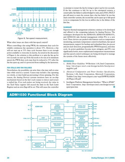
Figure 8. Fan-speed measurement.<br />
What other issues are there with fan-speed control?<br />
When controlling a fan using PWM, the minimum duty cycle for<br />
reliable continuous fan operation is about 33%. However, a fan<br />
will not start up at 33% duty cycle because there is not enough<br />
power available to overcome its inertia. As noted in the discussion<br />
of Figure 6, the solution to this problem is to spin the fan up for<br />
two seconds on start-up. If the fan needs to be run at its minimum<br />
speed, the PWM duty cycle may then be reduced to 33% after the<br />
fan has spun up, and it is protected from stalling by the hysteresis.<br />
FAN STALLS AND FAN FAILURES<br />
Nevertheless, the possibility can arise that a fan may stall at some<br />
time while used in a system. Causes may include a fan operating<br />
too slowly, or dust build-up preventing it from spinning. For this<br />
reason, the <strong>Analog</strong> <strong>Devices</strong> systems monitors have an on-chip<br />
mechanism based on the fan’s tach output to detect and restart<br />
a stalled fan. If no tach pulses are being received, the value in<br />
the Tach Value register will exceed the limit in the Tach Limit<br />
Register and an error flag will be set. This will cause the controller<br />
to attempt to restart the fan by trying to spin it up for two seconds.<br />
If the fan continues to fail, for up to five attempted restarts, a<br />
catastrophic fan failure is acknowledged to exist, and a FAN_FAULT<br />
pin will assert to warn the system that a fan has failed. In two-fan<br />
dual-controller systems, the second fan can be spun up to full speed<br />
to try to compensate for the loss in airflow due to the failure of the<br />
first fan.<br />
SUMMARY<br />
Superior thermal-management solutions continue to be developed<br />
and offered to the computing industry by <strong>Analog</strong> <strong>Devices</strong>. The<br />
techniques developed for the ADM1029, ADM1030/ADM1031,<br />
and ADM1026 take thermal management within PCs to a new<br />
level. These devices are packed with features such as temperature<br />
monitoring, automatic temperature control in hardware, fan-speed<br />
measurement, support for backup and redundant fans, fan-present<br />
and fan-fault detection, programmable PWM frequency, and duty<br />
cycle. As power guidelines become more stringent, and PCs run<br />
significantly hotter, more sophisticated temperature-measurement<br />
and fan-speed-control techniques are being developed to manage<br />
the systems of the future more effectively.<br />
REFERENCES<br />
1. Mobile Power Guidelines ’99 Revision 1.00, Intel Corporation.<br />
http://developer.intel.com/design/mobile/Intelpower/<br />
mpg99r1.pdf<br />
2. Advanced Configuration and Power Interface Specification,<br />
Revision 1.0b, Intel Corporation, Microsoft Corporation,<br />
Toshiba Corp. http://www.teleport.com/~acpi/DOWNLOADS/<br />
ACPIspec10b.pdf<br />
3. Intelligent Platform Management Interface: “What is IPMI?”<br />
Intel Corporation. http://developer.intel.com/design/servers/<br />
ipmi/ipmi.htm b<br />
ADM1030 Functional Block Diagram<br />
V CC<br />
NC<br />
NC<br />
ADM1030<br />
SLAVE<br />
ADDRESS<br />
REGISTER<br />
FAN<br />
CHARACTERISTICS<br />
REGISTER<br />
SERIAL BUS<br />
INTERFACE<br />
ADDRESS POINTER<br />
REGISTER<br />
ADD<br />
SDA<br />
SCL<br />
NC<br />
PWM_OUT<br />
PWM<br />
CONTROLLER<br />
FAN SPEED<br />
CONFIG REGISTER<br />
INTERRUPT<br />
MASK<br />
REGISTER<br />
INT/NTO<br />
TMIN/TRANGE<br />
REGISTER<br />
INTERRUPT<br />
STATUS<br />
REGISTER<br />
THERM<br />
FAN_FAULT<br />
TACH/AIN<br />
TACH SIGNAL<br />
CONDITIONING<br />
FAN SPEED<br />
COUNTER<br />
LIMIT<br />
COMPARATOR<br />
NC<br />
D<br />
D–/NTI<br />
BANDGAP<br />
TEMPERATURE<br />
SENSOR<br />
ANALOG<br />
MULTIPLEXER<br />
ADC<br />
2.5V<br />
BANDGAP<br />
REFERENCE<br />
VALUE AND LIMIT<br />
REGISTERS<br />
OFFSET REGISTER<br />
CONFIGURATION<br />
REGISTER<br />
GND<br />
NC= NO CONNECT<br />
20 <strong>Analog</strong> Dialogue 34-4 (2000)


