

Demystifying Auto-Zero Amplifiers—Part 1 - Analog Devices
Demystifying Auto-Zero Amplifiers—Part 1 - Analog Devices
Demystifying Auto-Zero Amplifiers—Part 1 - Analog Devices

You also want an ePaper? Increase the reach of your titles
YUMPU automatically turns print PDFs into web optimized ePapers that Google loves.
PULSEWIDTH MODULATION (PWM) GENERATION<br />
In typical ac motor-controller design, both hardware and software<br />
considerations are involved in the process of generating the PWM<br />
signals that are ultimately used to turn on or off the power devices<br />
in the three-phase inverter. In typical digital control environments,<br />
the controller generates a regularly timed interrupt at the PWM<br />
switching frequency (nominally 10 kHz to 20 kHz). In the interrupt<br />
service routine, the controller software computes new duty-cycle<br />
values for the PWM signals used to drive each of the three legs of<br />
the inverter. The computed duty cycles depend on both the<br />
measured state of the motor (torque and speed) and the desired<br />
operating state. The duty cycles are adjusted on a cycle-by-cycle<br />
basis in order to make the actual operating state of the motor follow<br />
the desired trajectory.<br />
Once the desired duty cycle values have been computed by the<br />
processor, a dedicated hardware PWM generator is needed to<br />
ensure that the PWM signals are produced over the next PWMand-controller<br />
cycle. The PWM generation unit typically consists<br />
of an appropriate number of timers and comparators that are<br />
capable of producing very accurately timed signals. Typically, 10-<br />
to-12 bit performance in the generation of the PWM timing<br />
waveforms is desirable. The PWM generation unit of the ADMC401<br />
is capable of an edge resolution of 38.5 ns, corresponding to<br />
approximately 11.3 bits of resolution at a switching frequency of<br />
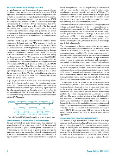
10 kHz. Typical PWM signals produced by the dedicated PWM<br />
generation unit of the ADMC401 are shown in Figure 2, for<br />
inverter leg A. In the figure, AH is the signal used to drive the<br />
high-side power device of inverter leg A, and AL is used to drive<br />
the low-side power device. The duty cycle effectively adjusts the<br />
average voltage applied to the motor on a cycle-by-cycle basis to<br />
achieve the desired control objective.<br />
In general, there is a small delay required between turning off one<br />
power device (say AL) and turning on the complementary power<br />
device (AH). This dead-time is required to ensure the device being<br />
turned off has sufficient time to regain its blocking capability before<br />
the other device is turned on. Otherwise a short circuit of the dc<br />
voltage could result. The PWM generation unit of the ADMC401<br />
contains the necessary hardware for automatic dead-time insertion<br />
into the PWM signals.<br />
CONTROLLER<br />
INTERRUPTS<br />
AH<br />
AL<br />
CONTROL PERIOD<br />
N<br />
CONTROL PERIOD<br />
N+1<br />
CONTROL PERIOD<br />
N+2<br />
50 100 150 200<br />
DUTY CYCLE, D1 DUTY CYCLE, D2 DUTY CYCLE, D3<br />
TIME<br />
s<br />
Figure 2. Typical PWM waveforms for a single inverter leg.<br />
General Structure of a Three-Phase AC Motor Controller<br />
Accurate control of any motor-drive process may ultimately be<br />
reduced to the problem of accurate control of both the torque and<br />
speed of the motor. In general, motor speed is controlled directly<br />
by measuring the motor’s speed or position using appropriate<br />
transducers, and torque is controlled indirectly by suitable control<br />
of the motor phase currents. Figure 3 shows a block diagram of a<br />
typical synchronous frame-current controller for a three-phase<br />
motor. The figure also shows the proportioning of tasks between<br />
software code modules and the dedicated motor-control<br />
peripherals of a motor controller such as the ADMC401. The<br />
controller consists of two proportional-plus-integral-plusdifferential<br />
(PID) current regulators that are used to control<br />
the motor current vector in a reference frame that rotates<br />
synchronously with the measured rotor position.<br />
Sometimes it may be desirable to implement a decoupling between<br />
voltage and speed that removes the speed dependencies and<br />
associated axes cross coupling from the control loop. The reference<br />
voltage components are then synthesized on the inverter using a<br />
suitable pulsewidth-modulation strategy, such as space vector<br />
modulation (SVM). It is also possible to incorporate some<br />
compensation schemes to overcome the distorting effects of the<br />
inverter switching dead time, finite inverter device on-state voltages<br />
and dc-link voltage ripple.<br />
The two components of the stator current vector are known as the<br />
direct-axis and quadrature-axis components. The direct-axis current<br />
controls the motor flux and is usually controlled to be zero with<br />
permanent-magnet machines. The motor torque may then be<br />
controlled directly by regulation of the quadrature axis component.<br />
Fast, accurate torque control is essential for high-performance<br />
drives in order to ensure rapid acceleration and deceleration—<br />
and smooth rotation down to zero speed under all load conditions.<br />
The actual direct and quadrature current components are obtained<br />
by first measuring the motor phase currents with suitable currentsensing<br />
transducers and converting them to digital, using an on-chip<br />
ADC system. It is usually sufficient to simultaneously sample just<br />
two of the motor line currents: since the sum of the three currents<br />
is zero, the third current can, when necessary, be deduced from<br />
simultaneous measurements of the other two currents.<br />
The controller software makes use of mathematical vector<br />
transformations, known as Park Transformations, that ensure that<br />
the three-phase set of currents applied to the motor is synchronized<br />
to the actual rotation of the motor shaft, under all operating<br />
conditions. This synchronism ensures that the motor always<br />
produces the optimal torque per ampere, i.e., operates at optimal<br />
efficiency. The vector rotations require real-time calculation of the<br />
sine and cosine of the measured rotor angle, plus a number of<br />
multiply-and-accumulate operations. The overall control-loop<br />
bandwidth depends on the speed of implementation of the closedloop<br />
control calculations—and the resulting computation of new<br />
duty-cycle values. The inherent fast computational capability of<br />
the 26-MIPS, 16-bit fixed-point DSP core makes it the ideal<br />
computational engine for these embedded motor-control<br />
applications.<br />
ANALOG-TO-DIGITAL CONVERSION REQUIREMENTS<br />
For control of high-performance ac servo-drives, fast, highaccuracy,<br />
simultaneous-sampling A/D conversion of the measured<br />
current values is required. Servo drives have a rated operation<br />
range—a certain power level that they can sustain continuously,<br />
with an acceptable temperature rise in the motor and power<br />
converter. Servo drives also have a peak rating—the ability to handle<br />
a current far in excess of the rated current for short periods of<br />
time. It is possible, for example, to apply up to six times the rated<br />
4 <strong>Analog</strong> Dialogue 34-6 (2000)


