

Demystifying Auto-Zero Amplifiers—Part 1 - Analog Devices
Demystifying Auto-Zero Amplifiers—Part 1 - Analog Devices
Demystifying Auto-Zero Amplifiers—Part 1 - Analog Devices

Create successful ePaper yourself
Turn your PDF publications into a flip-book with our unique Google optimized e-Paper software.
Advances in Video<br />
Encoders<br />
by Christine Bako<br />
Foreword to the reader: Video technology uses many special terms that<br />
may be unfamiliar to those not in the field. We’ve provided a 32-page<br />
glossary (Application Note 548, in PDF, 112 KB) to help readers who<br />
want to understand video terminology. It may be helpful to print out a<br />
copy to have on hand as a reference. A printed version of the glossary<br />
may also be ordered from Literature Distribution.<br />
INTRODUCTION<br />
Digital video signals from sources such as MPEG codecs must be<br />
appropriately encoded and converted to analog before they can<br />
be displayed by analog TVs and VCRs. In general, encoding means<br />
to convert from one format or signal to another. For video encoders,<br />
this means converting from 4:2:2 YCrCb digital video data into<br />
YUV, RGB, or CVBS analog video signals. YCrCb is a component<br />
digital signal, where Y is the luminance signal, which contains the<br />
black-and-white signal information, Cr is red minus the luminance<br />
(R-Y), and Cb is blue minus the luminance (B-Y). YUV is a scaled<br />
version of YCrCb. This scaling is necessary prior to combining<br />
the YUV signals into composite video, so that it will be contained<br />
within the amplitude limits of signal-processing and recording<br />
equipment. This YUV signal should not be confused with the analog<br />
YUV inputs found on high-end TVs. CVBS (Color, Video, Blank,<br />
and Sync) is a composite analog signal. In this format, a single<br />
analog video signal includes information on sync, color, and<br />
luminance. Composite signals are used in standard TVs and VCRs.<br />
The component formats provide a sharper picture with less noise<br />
than a composite signal because the modulation required to<br />
produce the CVBS signal is eliminated.<br />
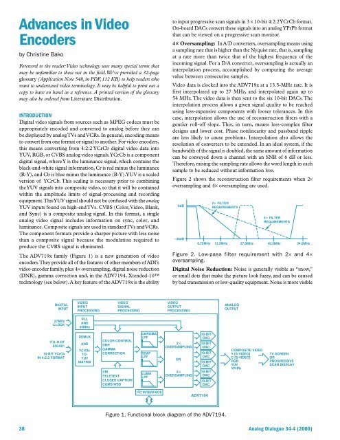
The ADV719x family (Figure 1) is a new generation of video<br />
encoders. They provide all of the features of other members of ADI’s<br />
video encoder family, plus 4× oversampling, digital noise reduction<br />
(DNR), gamma correction and, in the ADV7194, Xtended-10<br />
technology (see below). A key feature of the ADV719x is the ability<br />
to input progressive scan signals in 3 × 10-bit 4:2:2 YCrCb format.<br />
On-board DACs convert these signals into an analog YPrPb format<br />
that can be viewed on a progressive scan monitor.<br />
4 Oversampling: In A/D converters, oversampling means using<br />
a sampling rate that is higher than the Nyquist rate, that is, sampling<br />
at a rate more than twice that of the highest frequency of the<br />
incoming signal. For a D/A converter, oversampling is actually an<br />
interpolation process, accomplished by computing the average<br />
value between consecutive samples.<br />
Video data is clocked into the ADV719x at a 13.5-MHz rate. It is<br />
first interpolated up to 27 MHz, and interpolated again up to<br />
54 MHz. The video data is then sent to the six 10-bit DACs. The<br />
interpolation process allows a given signal quality to be reached<br />
using less-expensive components with looser tolerances. In this<br />
case, interpolation allows the use of reconstruction filters with a<br />
gentler roll-off slope. This, in turn, means less-complex filter<br />
designs and lower cost. Phase nonlinearity and passband ripple<br />
are less likely to cause problems. Interpolation also allows the<br />
resolution of converters to be extended. In an ideal system, if the<br />
bandwidth of the signal is doubled, the same amount of information<br />
can be conveyed down a channel with an SNR of 6 dB or less.<br />
Therefore, raising the sampling rate allows the word length in each<br />
sample to be reduced without information loss.<br />
Figure 2 shows the reconstruction filter requirements when 2×<br />
oversampling and 4× oversampling are used.<br />
0dB<br />
–30dB<br />
2 FILTER<br />
REQUIREMENTS<br />
4 FILTER<br />
REQUIREMENTS<br />
6.75MHz 13.5MHz 27.0MHz 40.5MHz 54.0MHz<br />
Figure 2. Low-pass filter requirement with 2× and 4×<br />
oversampling.<br />
Digital Noise Reduction: Noise is generally visible as “snow,”<br />
or small dots that make the picture look fuzzy, and can be caused<br />
by bad transmission or low-quality equipment. Noise is more visible<br />
DIGITAL<br />
INPUT<br />
VIDEO<br />
INPUT<br />
PROCESSING<br />
VIDEO<br />
SIGNAL<br />
PROCESSING<br />
VIDEO<br />
OUTPUT<br />
PROCESSING<br />
ANALOG<br />
OUTPUT<br />
27MHz<br />
CLOCK<br />
PLL<br />
AND<br />
54MHz<br />
ITU–R.BT<br />
656/601<br />
10-BIT YCrCb<br />
IN 4:2:2 FORMAT<br />
DEMUX<br />
AND<br />
YCrCb-<br />
TO-<br />
YUV<br />
MATRIX<br />
COLOR CONTROL<br />
DNR<br />
GAMMA<br />
CORRECTION<br />
VBI<br />
TELETEXT<br />
CLOSED CAPTION<br />
CGMS/WSS<br />
CHROMA<br />
LPF<br />
SSAF<br />
LPF<br />
LUMA<br />
LPF<br />
2<br />
OVERSAMPLING<br />
OR<br />
4<br />
OVERSAMPLING<br />
10-BIT<br />
DAC<br />
10-BIT<br />
DAC<br />
10-BIT<br />
DAC<br />
10-BIT<br />
DAC<br />
10-BIT<br />
DAC<br />
10-BIT<br />
DAC<br />
COMPOSITE VIDEO<br />
Y [S-VIDEO]<br />
C [S-VIDEO]<br />
RGB<br />
YUV<br />
YPrPb<br />
TV SCREEN<br />
OR<br />
PROGRESSIVE<br />
SCAN DISPLAY<br />
I 2 C INTERFACE<br />
ADV7194<br />
Figure 1. Functional block diagram of the ADV7194.<br />
38 <strong>Analog</strong> Dialogue 34-4 (2000)


