

Demystifying Auto-Zero Amplifiers—Part 1 - Analog Devices
Demystifying Auto-Zero Amplifiers—Part 1 - Analog Devices
Demystifying Auto-Zero Amplifiers—Part 1 - Analog Devices

Create successful ePaper yourself
Turn your PDF publications into a flip-book with our unique Google optimized e-Paper software.
Fundamentals of<br />
DSP-Based Control<br />
for AC Machines<br />
by Finbarr Moynihan,<br />
Embedded Control Systems Group<br />
INTRODUCTION<br />
High-performance servomotors are characterized by the need for<br />
smooth rotation down to stall, full control of torque at stall, and<br />
fast accelerations and decelerations. In the past, variable-speed<br />
drives employed predominantly dc motors because of their<br />
excellent controllability. However, modern high-performance<br />
motor drive systems are usually based on three-phase ac motors,<br />
such as the ac induction motor (ACIM) or the permanent-magnet<br />
synchronous motor (PMSM). These machines have supplanted<br />
the dc motor as the machine of choice for demanding servomotor<br />
applications because of their simple robust construction, low<br />
inertia, high output-power-to-weight ratios, and good performance<br />
at high speeds of rotation.<br />
The principles of vector control are now well established for<br />
controlling these ac motors; and most modern high-performance<br />
drives now implement digital closed-loop current control. In such<br />
systems, the achievable closed-loop bandwidths are directly related<br />
to the rate at which the computationally intensive vector-control<br />
algorithms and associated vector rotations can be implemented in<br />
real time. Because of this computational burden, many highperformance<br />
drives now use digital signal processors (DSPs) to<br />
implement the embedded motor- and vector-control schemes. The<br />
inherent computational power of the DSP permits very fast cycle<br />
times and closed-loop current control bandwidths (between 2 and<br />
4 kHz) to be achieved.<br />
The complete current control scheme for these machines also<br />
requires a high-precision pulsewidth modulation (PWM) voltagegeneration<br />
scheme and high-resolution analog-to-digital (A/D)<br />
conversion (ADC) for measurement of the motor currents. In order<br />
to maintain smooth control of torque down to zero speed, rotor<br />
position feedback is essential for modern vector controllers.<br />
Therefore, many systems include rotor-position transducers, such<br />
as resolvers and incremental encoders. We describe here the<br />
fundamental principles behind the implementation of highperformance<br />
controllers (such as the ADMC401) for three-phase<br />
ac motors—combining an integrated DSP controller, with a<br />
powerful DSP core, flexible PWM generation, high-resolution<br />
A/D conversion, and an embedded encoder interface.<br />
VARIABLE SPEED CONTROL OF AC MACHINES<br />
Efficient variable-speed control of three-phase ac machines requires<br />
the generation of a balanced three-phase set of variable voltages<br />
with variable frequency. The variable-frequency supply is typically<br />
produced by conversion from dc using power-semiconductor<br />
devices (typically MOSFETs or IGBTs) as solid-state switches. A<br />
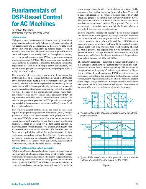
commonly-used converter configuration is shown in Figure 1a. It<br />
is a two-stage circuit, in which the fixed-frequency 50- or 60-Hz<br />
ac supply is first rectified to provide the dc link voltage, V D , stored<br />
in the dc link capacitor. This voltage is then supplied to an inverter<br />
circuit that generates the variable-frequency ac power for the motor.<br />
The power switches in the inverter circuit permit the motor<br />
terminals to be connected to either V D or ground. This mode of<br />
operation gives high efficiency because, ideally, the switch has zero<br />
loss in both the open and closed positions.<br />
By rapid sequential opening and closing of the six switches (Figure<br />
1a), a three-phase ac voltage with an average sinusoidal waveform<br />
can be synthesized at the output terminals. The actual output<br />
voltage waveform is a pulsewidth modulated (PWM) highfrequency<br />
waveform, as shown in Figure 1b. In practical inverter<br />
circuits using solid-state switches, high-speed switching of about<br />
20 kHz is possible, and sophisticated PWM waveforms can be<br />
generated with all voltage harmonic components at very high<br />
frequencies; well above the desired fundamental frequencies—<br />
nominally in the range of 0 Hz to 250 Hz.<br />
The inductive reactance of the motor increases with frequency so<br />
that the higher-order harmonic currents are very small, and nearsinusoidal<br />
currents flow in the stator windings. The fundamental<br />
voltage and output frequency of the inverter, as indicated in Figure<br />
1b, are adjusted by changing the PWM waveform using an<br />
appropriate controller. When controlling the fundamental output<br />
voltage, the PWM process inevitably modifies the harmonic content<br />
of the output voltage waveform. A proper choice of modulation<br />
strategy can minimize these harmonic voltages and their associated<br />
harmonic effects and high-frequency losses in the motor.<br />
THREE-<br />
PHASE<br />
60Hz<br />
MAINS<br />
RECTIFIER<br />
V D<br />
N<br />
INVERTER<br />
A B C<br />
a. Typical configuration of power converter used to drive threephase<br />
ac motors.<br />
FUNDAMENTAL<br />
MOTOR<br />
PHASE<br />
VOLTAGE<br />
V AB<br />
V AN<br />
V BN<br />
DESIRED FREQUENCY<br />
DESIRED<br />
AMPLITUDE<br />
b. Typical PWM waveforms in the generation of a variablevoltage,<br />
variable-frequency supply for the motor.<br />
Figure 1.<br />
M<br />
<strong>Analog</strong> Dialogue 34-6 (2000) 3


