

Pro 501st Airless Paint Sprayer - Graco Inc.
Pro 501st Airless Paint Sprayer - Graco Inc.
Pro 501st Airless Paint Sprayer - Graco Inc.

Create successful ePaper yourself
Turn your PDF publications into a flip-book with our unique Google optimized e-Paper software.
INSTRUCTIONS-PARTS LIST<br />
INSTRUCTIONS<br />
This manual contains important<br />
warnings and information.<br />
READ AND KEEP FOR REFERENCE.<br />
308–256<br />
Rev. D<br />
Supersedes Rev. B<br />
and PCN C<br />
ELECTRIC, 120 VAC<br />
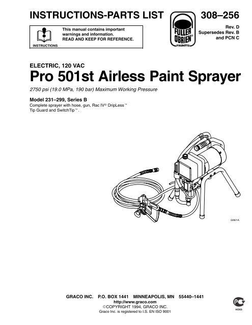
<strong>Pro</strong> <strong>501st</strong> <strong>Airless</strong> <strong>Paint</strong> <strong>Sprayer</strong><br />
2750 psi (19.0 MPa, 190 bar) Maximum Working Pressure<br />
Model 231–299, Series B<br />
Complete sprayer with hose, gun, Rac IV DripLess<br />
Tip Guard and SwitchTip.<br />
02821A<br />
GRACO INC. P.O. BOX 1441 MINNEAPOLIS, MN 55440–1441<br />
http://www.graco.com<br />
COPYRIGHT 1994, GRACO INC.<br />
<strong>Graco</strong> <strong>Inc</strong>. is registered to I.S. EN ISO 9001
Warnings . . . . . . . . . . . . . . . . . . . . . . . . . . . . . . . . . . . . . 2<br />
Setup . . . . . . . . . . . . . . . . . . . . . . . . . . . . . . . . . . . . . . . . 6<br />
Operation . . . . . . . . . . . . . . . . . . . . . . . . . . . . . . . . . . . . . 7<br />
Startup . . . . . . . . . . . . . . . . . . . . . . . . . . . . . . . . . . . . . . . 9<br />
Shutdown and Care . . . . . . . . . . . . . . . . . . . . . . . . . . 11<br />
Flushing . . . . . . . . . . . . . . . . . . . . . . . . . . . . . . . . . . . . . 12<br />
Warning Symbol<br />
WARNING<br />
This symbol alerts you to the possibility of serious<br />
injury or death if you do not follow the instructions.<br />
EQUIPMENT MISUSE HAZARD<br />
Table of Contents<br />
Symbols<br />
Troubleshooting . . . . . . . . . . . . . . . . . . . . . . . . . . . . . 13<br />
Repair . . . . . . . . . . . . . . . . . . . . . . . . . . . . . . . . . . . . . . . 18<br />
Parts . . . . . . . . . . . . . . . . . . . . . . . . . . . . . . . . . . . . . . . . 32<br />
Technical Data . . . . . . . . . . . . . . . . . . . . . . . . . . . . . . . 35<br />
Warranty . . . . . . . . . . . . . . . . . . . . . . . . . . . . . . . . . . . . 36<br />
<strong>Graco</strong> Phone Number . . . . . . . . . . . . . . . . . . . . . . . . 36<br />
Caution Symbol<br />
CAUTION<br />
This symbol alerts you to the possibility of damage to<br />
equipment if the you do not follow the instructions.<br />
WARNING<br />
INSTRUCTIONS<br />
Equipment misuse can cause the equipment to rupture or malfunction and result in serious injury.<br />
<br />
<br />
<br />
<br />
<br />
<br />
<br />
<br />
<br />
<br />
<br />
<br />
<br />
This equipment is for professional use only.<br />
Read all instruction manuals, tags, and labels before operating the equipment.<br />
Use the equipment only for its intended purpose. If you are not sure, call your <strong>Graco</strong> distributor.<br />
Do not alter or modify this equipment. Use only genuine <strong>Graco</strong> parts<br />
Check equipment daily. Repair or replace worn or damaged parts immediately.<br />
Do not exceed the maximum working pressure of the lowest rated system component. Refer to the<br />
Technical Data on page 35 for the maximum working pressure of this equipment.<br />
Use fluids and solvents compatible with the equipment wetted parts. Refer to the Technical Data<br />
section of all equipment manuals. Read the fluid and solvent manufacturer’s warnings.<br />
Do not use hoses to pull equipment.<br />
Route hoses away from traffic areas, sharp edges, moving parts, and hot surfaces. Do not expose<br />
<strong>Graco</strong> hoses to temperatures above 82C (180F) or below –40C (–40F).<br />
Do not lift pressurized equipment.<br />
Comply with all applicable local, state, and national fire, electrical, and safety regulations.<br />
Wear hearing protection when operating this equipment.<br />
Do not use 1,1,1–trichloroethane, methylene chloride, other halogenated hydrocarbon solvents or<br />
fluids containing such solvents in pressurized aluminum equipment. Such use could result in a<br />
chemical reaction, with the possibility of explosion.
INJECTION HAZARD<br />
WARNING<br />
Spray from the gun, leaks or ruptured components can inject fluid into your body and cause extremely<br />
serious injury, including the need for amputation. Fluid splashed in the eyes or on the skin can also<br />
cause serious injury.<br />
<br />
<br />
<br />
<br />
<br />
<br />
<br />
<br />
<br />
<br />
<br />
<br />
<br />
Fluid injected into the skin may look like just a cut, but it is a serious injury. Get immediate medical<br />
attention.<br />
Do not point the gun at anyone or at any part of the body.<br />
Do not put your hand or fingers over the spray tip.<br />
Do not stop or deflect leaks with your hand, body, glove or rag.<br />
Do not “blow back” fluid; this is not an air spray system.<br />
Always have the tip guard and the trigger guard on the gun when spraying.<br />
Check the gun diffuser operation weekly. Refer to the gun manual.<br />
Be sure the gun trigger safety operates before spraying.<br />
Lock the gun trigger safety when you stop spraying.<br />
Follow the Pressure Relief <strong>Pro</strong>cedure on page 9 if the spray tip clogs and before cleaning,<br />
checking or servicing the equipment.<br />
Tighten all fluid connections before operating the equipment.<br />
Check the hoses, tubes, and couplings daily. Replace worn or damaged parts immediately. Do not<br />
repair high pressure couplings; you must replace the entire hose.<br />
Fluid hoses must have spring guards on both ends, to help protect them from rupture caused by<br />
kinks or bends near the couplings.<br />
TOXIC FLUID HAZARD<br />
Hazardous fluid or toxic fumes can cause serious injury or death if splashed in the eyes or on the skin,<br />
inhaled, or swallowed.<br />
<br />
<br />
<br />
Know the specific hazards of the fluid you are using.<br />
Store hazardous fluid in an approved container. Dispose of hazardous fluid according to all local,<br />
state and national guidelines.<br />
Always wear protective eyewear, gloves, clothing and respirator as recommended by the fluid and<br />
solvent manufacturer.<br />
FUEL HAZARD<br />
The fuel used in this unit is combustible and when spilled on a hot surface can ignite and cause a fire.<br />
<br />
Do not fill the fuel tank while the engine is running or hot.<br />
EXHAUST HAZARD<br />
The exhaust contains poisonous carbon monoxide which is colorless and odorless.<br />
<br />
Do not operate this equipment in a closed building.
FIRE AND EXPLOSION HAZARD<br />
WARNING<br />
Improper grounding, poor ventilation, open flames or sparks can cause a hazardous condition and result<br />
in a fire or explosion and serious injury.<br />
<br />
<br />
<br />
<br />
<br />
<br />
<br />
<br />
<br />
<br />
If there is any static sparking or you feel an electric shock while using this equipment, stop spraying<br />
immediately. Do not use the equipment until you identify and correct the problem.<br />
<strong>Pro</strong>vide fresh air ventilation to avoid the buildup of flammable fumes from solvents or the fluid<br />
being sprayed.<br />
Keep the spray area free of debris, including solvent, rags, and gasoline.<br />
Disconnect all electrical equipment in the spray area.<br />
Extinguish all open flames or pilot lights in the spray area.<br />
Do not smoke in the spray area.<br />
Do not turn on or off any light switch in the spray area while operating or if fumes are present.<br />
Do not operate a gasoline engine in the spray area.<br />
Ground the sprayer to a true earth ground with the ground wire and clamp (supplied).<br />
Use only electrically conductive hoses.<br />
MOVING PARTS HAZARD<br />
Moving parts can pinch or amputate your fingers.<br />
<br />
<br />
Keep clear of all moving parts when starting or operating the pump.<br />
Before servicing the equipment, follow the Pressure Relief <strong>Pro</strong>cedure on page 9 to prevent the<br />
equipment from starting unexpectedly.<br />
NOTE: This is an example of the DANGER label on your sprayer . This label is available in other languages, free of<br />
charge. See page 34 to order.<br />
FIRE AND<br />
EXPLOSION HAZARD<br />
SKIN INJECTION<br />
HAZARD<br />
Spray painting, flushing or cleaning equipment with flammable liquids<br />
in confined areas can result in fire or explosion.<br />
Use outdoors or in extremely well ventilated areas. Ground equipment,<br />
hoses, containers and objects being sprayed.<br />
Avoid all ignition sources such as static electricity from plastic drop<br />
cloths, open flames such as pilot lights, hot objects such as cigarettes,<br />
arcs from connecting or disconnecting power cords or turning<br />
light switches on and off.<br />
Failure to follow this warning can result in death or serious injury.<br />
Liquids can be injected into the body by high pressure airless spray<br />
or leaks – especially hose leaks.<br />
Keep body clear of the nozzle. Never stop leaks with any part of the<br />
body. Drain all pressure before removing parts.Avoid accidental triggering<br />
of gun by always setting safety latch when not spraying.<br />
Never spray without a tip guard.<br />
In case of accidental skin injection, seek immediate<br />
“Surgical Treatment”.<br />
Failure to follow this warning can result in amputation or serious<br />
injury.<br />
READ AND UNDERSTAND ALL LABELS AND INSTRUCTION MANUALS BEFORE USE
Notes
Setup<br />
<br />
1/4 npsm(m) fluid outlet<br />
32<br />
<br />
<br />
<br />
Do not install any shutoff device here<br />
Rotate clockwise to increase pressure<br />
Shown in closed or spray position<br />
<br />
64<br />
33<br />
<br />
Fill 1/3 full with TSL<br />
74<br />
<br />
<br />
28<br />
52<br />
<br />
102<br />
<br />
Fig. 1<br />
67<br />
02821A<br />
WARNING<br />
If you supply your own hoses and spray gun, be<br />
sure the hoses are electrically conductive, that the<br />
gun has a tip guard, and that each part is rated for<br />
at least 2750 psi (19.5 MPa, 195 bar) Working<br />
Pressure. This is to reduce the risk of serious injury<br />
caused by static sparking, fluid injection or overpressurization<br />
and rupture the hose or gun.<br />
CAUTION<br />
To avoid damaging the pressure control, which may<br />
result in poor equipment performance and component<br />
damage, follow these precautions.<br />
1. Always use a nylon spray hose at least 50 ft (15<br />
m) long.<br />
2. Never use a wire braid hose as it is too rigid to<br />
act as a pulsation dampener.<br />
3. Never install any shutoff device between the<br />
pump and the hose. See Fig. 1.<br />
1. Connect the hose (74) and gun (67) and screw it<br />
onto the outlet nipple (28). Do not use thread<br />
sealant, and do not install the spray tip yet.<br />
2. Fill the wet-cup (102). Pry off the wet-cup seal.<br />
Fill the cup 1/3 full with <strong>Graco</strong> Throat Seal Liquid<br />
(TSL), supplied. Install the wet-cup seal.<br />
3. Plug in the sprayer. Be sure the ON/OFF switch<br />
(52) is OFF. Plug the cord into a grounded outlet at<br />
least 20 feet away from the spray area.<br />
4. Check the electrical service. Be sure it is 120 V,<br />
60HzAC, 15 Amp (minimum). Use a properly<br />
grounded outlet. Do not remove the third (grounding)<br />
prong of the power supply cord, and do not<br />
use an adapter.<br />
Use a 3-wire, minimum 12 ga (16 AWG), 15 amp<br />
extension cord up to 150 ft. (45 m) long. Longer<br />
lengths affect sprayer performance.
Setup<br />
5. Ground the sprayer and spray system.<br />
e. Fluid supply container: according to local code.<br />
WARNING<br />
To reduce the risk of static sparking, ground the<br />
pump and all other equipment used or located in<br />
the spray area. Check your local electrical code for<br />
detailed grounding instructions for your area and<br />
type of equipment. Ground all of this equipment.<br />
a. <strong>Sprayer</strong>: plug into a properly grounded outlet.<br />
Do not use an adapter. Extension cords must<br />
have three wires and be rated for at least 15<br />
amps.<br />
b. Fluid hoses: use only grounded hoses with a<br />
maximum of 500 ft (150 m) combined hose<br />
length to ensure grounding continuity.<br />
c. Spray gun: obtain grounding through connection<br />
to a properly grounded fluid hose and<br />
sprayer.<br />
d. Object being sprayed: according to local code.<br />
f. All solvent pails used when flushing, according<br />
to local code. Use only metal pails, which are<br />
conductive. Do not place the pail on a nonconductive<br />
surface, such as paper or cardboard,<br />
which interrupts the grounding continuity.<br />
g. To maintain grounding continuity when flushing<br />
or relieving pressure, always hold a metal part<br />
of the gun firmly to the side of a grounded<br />
metal pail, then trigger the gun.<br />
6. Flush the pump to remove the oil which was left<br />
in to protect the pump parts after factory testing.<br />
See page 12.<br />
7. Prepare the paint according to the manufacturer’s<br />
recommendations. Remove any paint skin. Stir the<br />
paint to mix pigments. Strain the paint through a<br />
fine nylon mesh bag (available at most paint<br />
dealers) to remove particles that could clog the<br />
gun filter or spray tip. This is an important step<br />
toward trouble-free spraying.<br />
Operation<br />
How to Use the Gun Trigger Safety<br />
When locked, the gun trigger safety prevents the gun<br />
from accidental triggering. See Fig. 2.<br />
WARNING<br />
If the gun sprays when the gun trigger safety is<br />
locked, adjust the gun. See manual 307–614,<br />
supplied.<br />
How to Use the Pressure Drain Valve<br />
Use the pressure drain valve to relieve fluid pressure<br />
from the pump and to help prime the pump. If the valve<br />
senses an over pressure condition, it opens automatically<br />
to relieve fluid pressure. If this happens, stop<br />
spraying immediately, shut off and unplug the sprayer.<br />
Determine the cause of the problem and correct it<br />
before operating the sprayer again. Refer also to<br />
Troubleshooting, page 13. See Fig. 3.<br />
<br />
<br />
Open or drain, position<br />
Closed, or spray position<br />
<br />
<br />
Locked<br />
Unlocked<br />
<br />
<br />
<br />
<br />
Fig. 2<br />
Fig. 3<br />
02825A
Operation<br />
WARNING<br />
INJECTION HAZARD<br />
To reduce the risk of serious injury,<br />
whenever you are instructed to relieve<br />
pressure, follow the Pressure Relief<br />
<strong>Pro</strong>cedure on page 9.<br />
How to Use the Pressure Control<br />
The pressure control controls the motor operation so<br />
the sprayer maintains constant fluid pressure at the<br />
pump outlet. Turn the pressure control knob fully<br />
counterclockwise to obtain the minimum setting. Turn<br />
the knob clockwise to increase pressure. See Fig. 4.<br />
The tip guard alerts you to the risk and helps prevent<br />
placing any part of the body close to the spray tip. The<br />
tip guard also adjusts the vertical or horizontal spray<br />
pattern. See page 10. The tip guard holds a reversing<br />
spray tip. The tip is in the spraying position when the<br />
tip handle points forward. See Fig. 5.<br />
Clean the front of the tip frequently during the day’s<br />
operation. First, relieve the pressure.<br />
<br />
<br />
–<br />
+<br />
<br />
<br />
Tip handle shown in<br />
spraying position.<br />
Turn handle 180,<br />
trigger gun to clear clog<br />
Fig. 5<br />
<br />
Fig. 4<br />
02824A<br />
How to Remove a Tip Clog<br />
How to Use the RAC IV Tip Guard<br />
WARNING<br />
To reduce the risk of serious injury from fluid injection:<br />
Never operate the spray gun with the tip guard<br />
removed.<br />
Do not hold your hand, body, or a rag in front of the<br />
spray tip when cleaning or checking a clogged tip.<br />
Always point the gun toward the ground or into a<br />
pail when checking to see if the tip is clear.<br />
Do not try to “blow back” paint; this is not and air<br />
spray sprayer.<br />
1. Release the gun trigger. Lock the safety latch.<br />
Rotate the RAC IV tip handle 180. See Fig. 5.<br />
2. Unlock the safety latch. Trigger the gun into a pail<br />
or onto the ground to remove the clog.<br />
3. Lock the safety latch. Rotate the tip handle to the<br />
spraying position.<br />
4. If the tip is still clogged, lock the safety latch, shut<br />
off and unplug the sprayer, and open the pressure<br />
drain valve to relieve pressure. Clean the spray tip<br />
as shown in manual 307–848, supplied.
Startup<br />
Pressure Relief <strong>Pro</strong>cedure<br />
WARNING<br />
INJECTION HAZARD<br />
The system pressure must be manually<br />
relieved to prevent the system from<br />
starting or spraying accidentally. Fluid<br />
under high pressure can be injected through the<br />
skin and cause serious injury. To reduce the risk of<br />
an injury from injection, splashing fluid, or moving<br />
parts, follow the Pressure Relief <strong>Pro</strong>cedure<br />
whenever you:<br />
are instructed to relieve the pressure,<br />
stop spraying,<br />
check or service any of the system equipment,<br />
or install or clean the spray tip.<br />
1. Lock the gun trigger safety.<br />
2. Turn the ON/OFF switch to OFF.<br />
3. Unplug the power supply cord.<br />
4. Unlock the trigger safety. Hold a metal part of the<br />
gun firmly to the side of a grounded metal pail, and<br />
trigger the gun to relieve the pressure.<br />
5. Lock the gun trigger safety.<br />
6. Open the pressure drain valve, having a container<br />
ready to catch the drainage. Leave the valve open<br />
until you are ready to spray again.<br />
If you suspect that the spray tip or hose is completely<br />
clogged, or that pressure has not been fully relieved<br />
after following the steps above, VERY SLOWLY<br />
loosen the tip guard retaining nut or hose end coupling<br />
to relieve the pressure gradually, then loosen completely.<br />
Now clear the tip or hose.<br />
Startup <strong>Pro</strong>cedure<br />
Use this procedure each time you start the sprayer to<br />
help ensure the sprayer is ready to operate and that<br />
you start it safely.<br />
NOTE: If this is a first-time startup, flush the sprayer.<br />
See page 12.<br />
NOTE: Refer to Fig. 1 and other figures referenced in<br />
the text as you start the sprayer.<br />
1. Open the pressure drain valve (42).<br />
2. Do not install the spray tip until the pump is<br />
primed.<br />
3. Put the suction hose (32) into the paint. If you<br />
are pumping from a pail, push the drain hose (33)<br />
down below the top of the pail to avoid splashing<br />
paint wen the drain valve is opened.<br />
4. Turn the pressure knob (64) to the minimum<br />
setting.<br />
5. Unlock the gun trigger safety. See Fig. 2, page<br />
7.<br />
CAUTION<br />
To reduce the risk of damage to the displacement<br />
pump packings, never run the pump without fluid in<br />
it for more than 30 seconds.<br />
6. To prime the pump, turn the sprayer switch (52)<br />
on. Slowly increase the pressure until the sprayer<br />
starts. When fluid comes from the pressure drain<br />
valve, close the valve.<br />
WARNING<br />
To reduce the risk of static sparking and splashing<br />
when flushing, always remove the spray tip from<br />
the gun, and hold a metal part of the gun firmly to<br />
the side of, and aimed into, a grounded metal pail.<br />
See Ref. A in Fig. 6.<br />
A<br />
Fig. 6 01024<br />
7. To prime the hose, lower the pressure to reduce<br />
splashing. Hold a metal part of the gun firmly<br />
against and aimed into a grounded metal pail. See<br />
the WARNING above. Hold the trigger open and<br />
slowly increase the pressure until the pump starts.<br />
Keep the gun triggered until all air is forced out of<br />
the system and the fluid flows freely from the gun.<br />
Release the trigger and lock the gun trigger safety.
Setup<br />
8. Check all fluid connections for leaks. Relieve the<br />
pressure before tightening any connections.<br />
9. Install the spray tip. Lock the gun trigger safety<br />
first. See manual 307–848 for how to install the tip.<br />
10. Adjust the spray pattern.<br />
a. <strong>Inc</strong>rease the pressure just until spray from the<br />
gun is completely atomized. To avoid excessive<br />
overspray and fogging, and to extent tip<br />
and sprayer life, always use the lowest pressure<br />
required to get the desired results.<br />
NOTE: Spray patterns will change as tips wear.<br />
Change the spray tip if adjusting the pressure will not<br />
improve the spray pattern.<br />
<br />
A<br />
b. If more coverage is needed, use a larger tip<br />
rather than increasing the pressure.<br />
c. Test the spray pattern. To adjust the direction<br />
of the spray pattern, lock the gun trigger safety<br />
and loosen the retaining nut (A). Position the<br />
tip guard horizontally for a horizontal pattern or<br />
vertically for a vertical pattern. Hold the tip<br />
guard in place while tightening the retaining<br />
nut. See Fig. 7.<br />
<br />
<br />
Fig. 7<br />
For a vertical<br />
spray pattern<br />
For a horizontal<br />
spray pattern
Shutdown and Care<br />
WARNING<br />
INJECTION HAZARD<br />
To reduce the risk of serious injury,<br />
whenever you are instructed to relieve<br />
pressure, follow the Pressure Relief<br />
<strong>Pro</strong>cedure on page 9.<br />
1. Check the packing nut/wet-cup daily (102).<br />
Relieve the pressure and unplug the sprayer.<br />
Keep the wet-cup 1/3 full of TSL at all times to<br />
help prevent fluid buildup on the piston rod and<br />
premature wear of packings.<br />
2. Tighten the packing nut/wet-cup (102) just<br />
enough to stop leakage. Over-tightening causes<br />
binding and excessive packing wear. Use a round<br />
punch or brass rod and a light hammer to adjust<br />
the nut. See Fig. 8.<br />
7. For very short shutoff periods, leave the suction<br />
hose in the paint, relieve the pressure, and clean<br />
the spray tip.<br />
8. Coil the hose when storing it, even for overnight,<br />
to help protect the hose from kinking, abrasion,<br />
coupling damage, etc.<br />
<br />
Turn packing<br />
nut clockwise to<br />
tighten<br />
102<br />
+<br />
–<br />
3. Clean the gun’s fluid filter often and whenever<br />
the gun is stored. Relieve the pressure first.<br />
Refer to manual 307–614.<br />
4. Periodically clean paint residue from the pressure<br />
transducer (29) vent hole area. See Fig. 8.<br />
Replace the transducer when leakage is excessive.<br />
See page 29.<br />
Fig. 8<br />
Vent hole<br />
02829A<br />
5. Lubricate the bearing housing after every 100<br />
hours of operation. Remove the front cover. Fill the<br />
bearing housing cavity (A) with SAE 10 non-detergent<br />
oil. See Fig. 9.<br />
<br />
29<br />
A<br />
6. Flush the sprayer at the end of each work day<br />
and fill it with mineral spirits to help prevent pump<br />
corrosion and freezing. See page 12.<br />
CAUTION<br />
To prevent pump corrosion, and to reduce the<br />
chance of fluid freezing in the pump in cold weather,<br />
never leave water or any type of paint in the sprayer<br />
when it is not in use. Freezing can seriously damage<br />
the spray or result in a loss of pressure or<br />
stalling.<br />
Fig. 9<br />
02827A
Flushing<br />
When to Flush<br />
WARNING<br />
INJECTION HAZARD<br />
To reduce the risk of serious injury,<br />
whenever you are instructed to relieve<br />
pressure, follow the Pressure Relief<br />
<strong>Pro</strong>cedure on page 9.<br />
1. Before using a new sprayer: flush out the oil<br />
which was left in to protect pump parts.<br />
Before using water-base paint: flush with mineral<br />
spirits followed by soapy water, and then a clean<br />
water flush.<br />
Before using oil-base paint: flush with mineral<br />
spirits only.<br />
2. Changing colors: flush with compatible solvent<br />
such as mineral spirits or water.<br />
3. Changing from water-base to oil-base paint:<br />
flush with warm, soapy water, and then mineral<br />
spirits.<br />
4. Changing from oil-base to water-base paint:<br />
flush with warm, soapy water, and then a clean<br />
water flush.<br />
5. Storage after using water-base paint: flush with<br />
water and then mineral spirits. Leave the system<br />
filled with mineral spirits. Relieve the pressure.<br />
Leave the drain valve open.<br />
CAUTION<br />
Never leave water or water-based fluids in the<br />
sprayer if there is a chance is could freeze. Push<br />
the water out with mineral spirits. Frozen fluids in<br />
the sprayer prevents it from being started and may<br />
cause serious damage.<br />
6. Startup after storage. Before using water-base<br />
paint, flush out the mineral spirits with soapy water<br />
and then clean water. When using oil-base paint,<br />
flush out the mineral spirits with the paint.<br />
How to Flush<br />
1. Relieve the pressure.<br />
2. Remove the spray tip and clean it separately.<br />
Remove the filter screen and reinstall the bowl,<br />
hand tight, without the screen. Clean the screen<br />
separately. See Fig. 10.<br />
3. Pour one-half gallon (2 liters) of compatible solvent<br />
into a grounded metal flushing pail. Put the suction<br />
hose in the pail.<br />
4. Open the pressure drain valve. See Fig. 3, page 7.<br />
5. To save the paint still in the pump and hose, follow<br />
Step 6, except put the drain hose in the paint pail.<br />
When solvent appears, close the drain valve. Put<br />
the drain hose in the flushing pail. Trigger the gun<br />
into the paint pail. When solvent appears, release<br />
the trigger. Continue with step 6.<br />
WARNING<br />
To reduce the risk of static sparking and splashing<br />
when flushing, always remove the spray tip from<br />
the gun, and hold a metal part of the gun firmly to<br />
the side of, and aimed into, a grounded metal pail.<br />
See Ref. A in Fig. 11.<br />
A<br />
Fig. 11 01024<br />
6. Lower the pressure setting. Turn on the sprayer.<br />
Maintaining metal-to-metal contact, trigger the gun<br />
into the flushing pail. Slowly increase the sprayer<br />
pressure until the pump starts. Keep the gun<br />
triggered until the solvent flows freely from the<br />
gun. Circulate the solvent to thoroughly clean the<br />
sprayer. Release the gun trigger. Lock the gun<br />
trigger safety.<br />
7. Open the drain valve and circulate the solvent<br />
through the drain hose to thoroughly clean it.<br />
Close the drain valve.<br />
8. Remove the suction hose from the pail. Unlock the<br />
gun trigger safety. Trigger the gun and run the<br />
pump a few seconds to push air into the hose. Do<br />
not run the pump dry for more than 30 seconds to<br />
avoid damaging the pump packings. Relieve the<br />
pressure.<br />
BOWL<br />
SCREEN<br />
9. Remove and clean the inlet strainer. Wipe paint off<br />
the suction hose and drain hose.<br />
10. Refer to When to Flush, Step 1 again. Relieve<br />
the pressure.<br />
Fig. 10<br />
<br />
11. Leave the drain valve open until you use the<br />
sprayer again.
WARNING<br />
INJECTION HAZARD<br />
To reduce the risk of serious injury,<br />
whenever you are instructed to relieve<br />
pressure, follow the Pressure Relief<br />
<strong>Pro</strong>cedure on page 9.<br />
Troubleshooting<br />
Check everything in the chart before disassembling the sprayer.<br />
Basic <strong>Pro</strong>blem Solving<br />
Check everything in the guide before disassembling the sprayer.<br />
TYPE OF PROBLEM<br />
WHAT TO CHECK<br />
If check is OK, go to next check<br />
Fluid pressure 1. Check pressure control knob setting. The pump<br />
won’t develop much pressure if it is at minimum<br />
setting (fully counterclockwise).<br />
2. Check for a clogged spray tip or fluid filter, if<br />
used. See page 8.<br />
WHAT TO DO<br />
When check is not OK, refer to this column<br />
1. Slowly increase pressure setting to see if<br />
motor starts.<br />
2. If tip is still clogged, relieve pressure; refer<br />
to separate gun or tip instruction manual<br />
for tip cleaning. Clean or replace filter<br />
element. See manual 308–249.<br />
Mechanical<br />
1. Check for frozen or hardened paint in pump<br />
(20). Using a screwdriver, carefully try to rotate<br />
fan at back of motor by hand. See page 17.<br />
2. Check pump connecting rod pin (17). It must be<br />
completely pushed into connecting rod (15),<br />
and retaining spring (18) must be firmly in connecting<br />
rod groove. See Fig. 18, page 20<br />
3. Check for motor damage. Remove drive housing<br />
assembly (11). See page 26. Try to rotate<br />
motor fan by hand.<br />
1. Thaw. Plug in sprayer and turn on.<br />
Slowly increase pressure setting to see if<br />
motor starts. If it doesn’t, see NOTE, below.<br />
2. Push pin into place and secure with<br />
spring retainer.<br />
3. Replace motor (4) if fan won’t turn. See<br />
page 24.<br />
Electrical 1. Check electrical supply with volt meter. Meter<br />
should read 105–125 VAC.<br />
2. Check extension cord for visible damage. Use<br />
a volt meter or test lamp at extension cord outlet<br />
to check.<br />
3. Check sprayer power supply cord (50) for visible<br />
damage such as broken insulation or wires.<br />
4. Check motor brushes for the following:<br />
a. Loose terminal screws.<br />
b. Broken or misaligned brush springs.<br />
c. Brushes binding in holders.<br />
d. Broken leads.<br />
e. Worn brushes.<br />
NOTE: The brushes do not wear at same rate<br />
on both sides of motor. Check both brushes.<br />
1. Reset building circuit breaker; replace<br />
building fuse. Try another outlet.<br />
2. Replace extension cord.<br />
3. Replace power supply cord.<br />
See page 25.<br />
4. Refer to page 19.<br />
a. Tighten.<br />
b. Replace broken spring and/or align<br />
spring with brush<br />
c. Clean brush holders. Remove carbon<br />
with small cleaning brush. Align brush<br />
leads with slot in brush holder to assure<br />
free vertical brush movement.<br />
d. Replace brushes<br />
e. Replace brushes if less than long.<br />
NOTE: Thaw sprayer if water or water–based paint has frozen in it, due to exposure to low temperatures, by placing in a warm<br />
area. Do not try to start sprayer until completely thawed or damage to motor and/or start board may occur. If paint hardened<br />
(dried) in sprayer, the pump packings (page 20) and/or pressure transducer (page 29) must be replaced.
Basic <strong>Pro</strong>blem Solving<br />
TYPE OF PROBLEM<br />
WHAT TO CHECK<br />
If check is OK, go to next check<br />
Electrical (continued) 5. Check motor armature commutator for burn<br />
spots, gouges and extreme roughness. Remove<br />
motor cover and brush inspection plates<br />
to check. See page 19.<br />
6. Check motor armature for shorts using armature<br />
tester (growler) or perform motor test.<br />
See page 17.<br />
7. Check leads from pressure control and motor to<br />
motor start board (47) to be sure they are securely<br />
fastened and properly mated.<br />
8. Check motor start board (47) by substituting<br />
with a good board. See page 25.<br />
WHAT TO DO<br />
When check is not OK, refer to this column<br />
5. Remove motor and have motor shop<br />
resurface commutator if possible. See<br />
page 24.<br />
6. Replace motor. See page 24.<br />
7. Replace loose terminals; crimp to leads.<br />
Be sure male terminal blades are straight<br />
and firmly connected to mating part.<br />
8. Replace board. See page 25.<br />
CAUTION: Do not perform this check until motor<br />
armature is determined to be good. A bad<br />
motor armature can burn out a good board.<br />
9. Check power supply cord (50). Disconnect<br />
black and white power cord terminals; connect<br />
volt meter to these leads. Plug in sprayer. Meter<br />
should read VAC. Unplug sprayer.<br />
10. Check ON/OFF switch (52). Disconnect the “L”<br />
wire between the motor start board (47) and<br />
switch and connect volt meter between exposed<br />
terminal on switch and power cord’s<br />
white wire. Plug in sprayer and turn ON. Meter<br />
should read VAC. Turn off and unplug sprayer.<br />
11. Check motor thermal cutout switch. Connect<br />
ohmmeter between motor’s red leads. Meter<br />
should read 1 ohm maximum.<br />
12. Remove pressure control (64) and check microswitch<br />
operation with ohmmeter:<br />
(1) With pressure knob at lowest setting and<br />
stem pushed into control, readings should<br />
be: white & black = 1 ohm max.<br />
white & red = open.<br />
(2) With pressure knob at highest setting,readings<br />
should be: white & black = open;<br />
white & red = 1 ohm max.<br />
9. Replace power supply cord. See page<br />
25.<br />
10. Replace ON/OFF switch. See page 25.<br />
11. Allow motor to cool. Correct cause of<br />
overheating. If switch remains open after<br />
motor cools, replace motor.<br />
12. Replace pressure control. See page 28.<br />
TYPE OF PROBLEM<br />
13. Check pressure transducer (29) for hardened<br />
paint or damaged or worn components. See<br />
page 29.<br />
Intermediate <strong>Pro</strong>blem Solving<br />
WHAT TO CHECK<br />
If check is OK, go to next check<br />
13. Replace transducer. See page 29. Thorough<br />
system flushing will help extend life<br />
of transducer.<br />
WHAT TO DO<br />
When check is not OK refer to this column<br />
Low output 1. Check for worn spray tip. 1. Follow Pressure Relief <strong>Pro</strong>cedure then<br />
replace tip. See your separate gun or tip<br />
manual.<br />
2. Be sure pump does not continue to stroke<br />
when gun trigger is released. Plug in and turn<br />
on sprayer. Prime with paint. Trigger gun momentarily,<br />
then release and lock safety latch.<br />
Relieve pressure, turn off and unplug sprayer.<br />
2. Service pump. See page 20.
Intermediate <strong>Pro</strong>blem Solving<br />
TYPE OF PROBLEM<br />
WHAT TO CHECK<br />
If check is OK, go to next check<br />
Low output (continued) 3. Release gun trigger. Observe resting position of<br />
pump rod (107).<br />
4. Check electrical supply with volt meter. Meter<br />
should read VAC.<br />
5. Check extension cord size and length; must be<br />
at least 3 wire and less than 150 ft (45 m).<br />
6. Check motor brushes. See Electrical – What To<br />
Check, item 4, on page 13<br />
7. Check motor start board (47) by substituting<br />
with a good board.<br />
WHAT TO DO<br />
When check is not OK, refer to this column<br />
3. If pump consistently comes to rest with<br />
rod (107) fully extended, the piston packings<br />
and/or piston valve may be worn.<br />
Service the pump. See page 20.<br />
4. Reset building circuit breaker; replace<br />
building fuse. Repair electrical outlet or<br />
try another outlet.<br />
5. Replace with a correct, grounded extension<br />
cord.<br />
6. See page 19.<br />
7. Replace board. See page 25.<br />
CAUTION: Do not perform this check until motor<br />
armature is determined to be good. A bad<br />
motor armature can burn out a good board.<br />
8. Check motor armature for shorts by using an<br />
armature tester (growler) or perform motor test.<br />
See page 17.<br />
Drain valve leaks 1. Check drain valve for correct torque and/or<br />
worn parts. Check for debris trapped on seat.<br />
8. Replace motor. See page 24.<br />
9. Tighten to 185 in–lb (21 N.m). Clean<br />
valve and replace with new gasket (42a)<br />
and sealant (42d). See page 31.<br />
Transducer leaks 1. Slight leakage from transducer is normal. 1. Periodically remove residue from its cylinder<br />
port. See page 29.<br />
No output: motor runs and<br />
pump strokes<br />
1. Check paint supply. 1. Refill and reprime pump.<br />
2. Check for clogged intake strainer. 2. Remove and clean, then reinstall.<br />
No output: motor runs but<br />
pump does not stroke<br />
3. Check for loose suction tube or fittings. See<br />
page 30.<br />
4. Check to see if intake valve ball and piston ball<br />
are seating properly. See page 20.<br />
5. Check for leaking around throat packing nut<br />
which may indicate worn or damaged packings.<br />
See page 20.<br />
6. Release gun trigger. Observe resting position of<br />
pump rod (107).<br />
1. Check displacement pump connecting rod pin<br />
(17). See Fig. 18, page 20.<br />
7. Check connecting rod assembly (15) for damage.<br />
See page 26.<br />
8. Be sure crank in drive housing rotates; plug in<br />
sprayer and turn on briefly to check. Turn off<br />
and unplug sprayer. See page 26.<br />
3. Tighten; use thread sealant on npt<br />
threads of inlet tube (38). Check for damaged<br />
o–ring (27).<br />
4. Remove intake valve and clean. Check<br />
ball and seat for nicks; replace as needed.<br />
See page 20. Strain paint before using<br />
to remove particles that could clog<br />
pump.<br />
5. Replace packings. See page 20. Also<br />
check piston valve seat for hardened<br />
paint or nicks and replace if necessary.<br />
Tighten packing nut/wet-cup.<br />
6. If pump consistently comes to rest with<br />
rod (107) fully extended, the piston packings<br />
and/or piston valve may be worn.<br />
Service the pump. See page 20.<br />
1. Replace pin if missing. Be sure retainer<br />
spring (18) is fully in groove all around<br />
connecting rod.<br />
7. Replace connecting rod assembly. See<br />
page 26.<br />
8. Check drive housing assembly for<br />
damage and replace if necessary. See<br />
page 26.
Intermediate <strong>Pro</strong>blem Solving<br />
TYPE OF PROBLEM<br />
WHAT TO CHECK<br />
If check is OK, go to next check<br />
Spray pattern variations 1. Spray tip worn beyond sprayer pressure<br />
capability.<br />
Motor is hot and runs<br />
intermittently<br />
WHAT TO DO<br />
When check is not OK, refer to this column<br />
1. Replace spray tip.<br />
NOTE: A smaller size tip will provide<br />
longer life.<br />
2. Check transducer (29) for wear or damage. 2. Replace transducer. See page 29.<br />
3. Check pressure control (64) for smooth<br />
operation.<br />
4. Check Low output section, page 15.<br />
1. Determine if sprayer was operated at high pressure<br />
with small tips, which causes excessive<br />
heat build up.<br />
3. Replace pressure control. See page 28.<br />
1. Decrease pressure setting or increase tip<br />
size.<br />
2. Be sure ambient temperature where sprayer is<br />
located is no more than and sprayer is not located<br />
in direct sun.<br />
2. Move sprayer to shaded, cooler area if<br />
possible.<br />
3. Check motor. 3. Replace motor. See page 24.<br />
Building circuit breaker opens<br />
as soon as sprayer switch is<br />
turned on.<br />
Circuit breaker opens after<br />
sprayer operates for 5 to 10<br />
minutes.<br />
Building circuit breaker<br />
opens as soon as sprayer<br />
is plugged into outlet and<br />
sprayer is NOT turned on.<br />
1. Check all electrical wiring for damaged insulation,<br />
and all terminals for loose fit or damage.<br />
Also check wires between pressure control and<br />
motor. See page 28.<br />
2. Check for missing motor brush inspection plate<br />
gasket (see page 17), bent terminal forks or<br />
other metal to metal contact points which could<br />
cause a short.<br />
3. Check motor armature for shorts. Use an armature<br />
tester (growler) or perform motor test. See<br />
page 17. Inspect windings for burns.<br />
4. Check motor start board (47) by substituting<br />
with a good board.<br />
CAUTION: Do not perform this check until<br />
motor armature is determined to be good. A<br />
bad motor armature can burn out a good board.<br />
1. Check ‘Basic <strong>Pro</strong>blems – Electrical’ on<br />
page 13.<br />
1. Check electrical supply with volt meter. Meter<br />
should read VAC.<br />
2. Check tightness of pump packing nut. Overtightening<br />
tightens packings on rod, restricts<br />
pump action, damages packings.<br />
1. Repair or replace any damaged wiring or<br />
terminals. Securely reconnect all wires.<br />
2. Correct faulty conditions.<br />
3. Replace motor. See page 24.<br />
4. Replace board. See page 25.<br />
1. If voltage is too high, do not operate<br />
sprayer until corrected.<br />
2. Loosen packing nut. Check for leaking<br />
around throat. Replace pump packings, if<br />
necessary. See page 20.<br />
3. Check for damaged motor. 3. Replace motor. See page 24.<br />
Unit will not run on generator<br />
but does run on AC<br />
power<br />
4. Check ON/OFF switch (52). Be sure sprayer is<br />
unplugged! Disconnect wires from switch.<br />
Check switch with ohmmeter. The reading<br />
should be infinity with ON/OFF switch OFF, and<br />
zero with switch ON.<br />
CAUTION: A short in motor circuit can damage<br />
switch and or motor start board (47).<br />
1. Check the generator’s “peak” voltage. This<br />
sprayer will not run if the peak voltage is above<br />
190V.<br />
4. Replace ON/OFF switch. See page 25.<br />
1. Use AC power or a different generator
Motor Test<br />
WARNING<br />
INJECTION HAZARD<br />
To reduce the risk of serious injury,<br />
whenever you are instructed to relieve<br />
pressure, follow the Pressure Relief<br />
<strong>Pro</strong>cedure on page 9.<br />
For checking armature, motor winding, and brush<br />
electrical continuity.<br />
B<br />
Setup<br />
A<br />
Remove the drive housing. See page 26. This is to<br />
ensure that any resistance you notice in the armature<br />
test is due to the motor and not to worn gears in the<br />
drive housing.<br />
Remove the motor brush inspection covers (A). See<br />
Fig. 12.<br />
Remove the junction box screws (56). Lower the<br />
junction box. Disconnect the two leads (C) from the<br />
motor to the board (47). See Fig. 13.<br />
Armature Short Circuit<br />
Remove the handle (24) and the fan cover (B). See<br />
Fig. 12.<br />
Fig. 12<br />
02829A<br />
Spin the motor fan by hand. If there are no shorts, the<br />
motor will coast two or three revolutions before coming<br />
to a complete stop. If the motor does not spin freely,<br />
the armature is shortened and the motor must be<br />
replaced. See page 24.<br />
MOTOR<br />
Armature, Brushes, and Motor Wiring<br />
Open Circuit Test (Continuity)<br />
Connect the two black motor leads together with a test<br />
lead. Turn the motor fan by hand at about two revolutions<br />
per second.<br />
When turning the fan on a DC motor, normally you<br />
sense an even, pulsing resistance. If there is irregular<br />
turning resistance, check and repair the following as<br />
needed: broken brush springs, brush leads, motor<br />
leads; loose brush terminal screws or motor lead<br />
terminals; worn brushes. See page 19.<br />
If there is still uneven or no turning resistance, replace<br />
the motor. See page 24.<br />
59<br />
Fig. 13<br />
BLACK/<br />
WHITE<br />
BLACK<br />
C<br />
47<br />
RED
General Repair Information<br />
Tool List<br />
WARNING<br />
INJECTION HAZARD<br />
To reduce the risk of serious injury,<br />
whenever you are instructed to relieve<br />
pressure, follow the Pressure Relief<br />
<strong>Pro</strong>cedure on page 9.<br />
These are tools required to service all parts of the<br />
sprayer.<br />
3/16” Allen wrench: gear housing, legs, handle<br />
3/8” Allen wrench: pump manifold<br />
#1 Phillips screwdriver junction box, pressure control,<br />
front cover<br />
3/8” socket wrench: motor mount<br />
5/8” socket wrench: drain valve, outlet fittings,<br />
on/off switch boot, piston<br />
13/16” socket wrench: drain valve<br />
1–1/4” socket wrench: pump inlet valve<br />
1/2” open end wrench: pump rod<br />
11/16” open end wrench: piston jam nut<br />
15/16” open end wrench: flats of inlet tube<br />
1–3/4” open end wrench: pump ham nut<br />
5/64” drive pin: drain valve pin<br />
3” needle nose pliers: wiring, on/off switch<br />
Hammer & punch: packing nut<br />
Torque wrenches: various fasteners<br />
1. When disconnecting wires in the junction box<br />
assembly, use needle nose pliers to separate<br />
mating connectors.<br />
2. When reconnecting the wires, be sure the flat<br />
blade of the insulated male connector is centered<br />
in the wrap-around blade of the female connector.<br />
CAUTION<br />
To reduce the risk of pressure control malfunction,<br />
be sure to properly mate connectors, and never pull<br />
on a wire to disconnect it. Pulling on a wire could<br />
loosen the connector from the wire.<br />
3. Route wire carefully through the drive housing<br />
and motor. Avoid pinching the wires between the<br />
junction box and the motor or pressure control.<br />
CAUTION<br />
Improper wire routing can result in poor sprayer<br />
performance or damage to the pressure control.<br />
4. Keep all screws, nuts, washers, gaskets, and<br />
electrical fittings removed during repair procedures.<br />
These parts are not normally provided with<br />
replacement assemblies.<br />
5. Test your repair before regular operation to be<br />
sure the problem is corrected.<br />
6. If the sprayer does not operate properly, verify<br />
that everything was done correctly. Also refer to<br />
Troubleshooting, pages 13–16, to help identify<br />
other possible problems and solutions.<br />
WARNING<br />
To reduce the risk of serious injury, including electric<br />
shock. Do not touch any moving parts or electrical<br />
parts with your fingers or a tool while inspecting<br />
the repair.<br />
Shut off the sprayer and unplug it as soon as you<br />
complete the inspection.<br />
Reinstall all covers, gaskets, screws, and washers<br />
before operating the sprayer.<br />
WARNING<br />
During operation, the motor and drive housing<br />
become very hot and could burn your skin if<br />
touched. Flammable materials spilled on the hot,<br />
bare motor could cause a fire or explosion.
WARNING<br />
INJECTION HAZARD<br />
To reduce the risk of serious injury,<br />
whenever you are instructed to relieve<br />
pressure, follow the Pressure Relief<br />
<strong>Pro</strong>cedure on page 9.<br />
NOTE: Replace brushes when worn to about 0.5 in<br />
(12.5 mm). Always check both brushes. Brush Repair<br />
Kit 236–967 is available for motors manufactured by<br />
Pacific Scientific. Consult Rev. A of this manual for<br />
repair kit and instructions if your motor has a Leeson<br />
motor.<br />
NOTE: Replacement brushes may last only half as<br />
long as the original ones. To maximize brush life, break<br />
in new brushes by operating the sprayer with no load<br />
as instructed in this procedure.<br />
1. Relieve the pressure Unplug the sprayer.<br />
2. Remove both inspection covers (A) and their<br />
gaskets. See Fig. 14.<br />
Motor Brushes<br />
a. Remove the pump connecting rod pin (17).<br />
See Fig. 18, page 20.<br />
b. With the sprayer OFF, turn the pressure control<br />
knob fully counterclockwise to minimum<br />
pressure. Plug in the sprayer.<br />
c. Turn the sprayer ON. Slowly increase the<br />
pressure until the motor is at full speed.<br />
d. Inspect the brush and commutator contact<br />
area for excessive arcing. Arcs should not<br />
circle around the commutator surface.<br />
WARNING<br />
Do not touch the brushes, leads, springs, or brush<br />
holders while the sprayer is plugged in to reduce<br />
the risk of electric shock and serious injury.<br />
11. Install the brush inspection covers and gaskets.<br />
12. Break in the brushes. Operate the sprayer for at<br />
least one hour with no load. Install the pump<br />
connecting rod pin.<br />
A<br />
<br />
<br />
Motor lead; do not disconnect<br />
Minimum 0.5” (12.5 mm)<br />
Fig. 14<br />
02831A<br />
<br />
3. Push in the spring clip (F) and release its hook (G)<br />
from the brush holder (B). Pull out the spring clip.<br />
See Fig. 15.<br />
F<br />
G<br />
H<br />
C<br />
<br />
4. Slide off the brush lead terminal (E) off the blade<br />
connector. Remove the old brush (C). See Fig. 15.<br />
5. Inspect the commutator for excessive pitting,<br />
burning, or gouging. A black color on the commutator<br />
is normal. Have the commutator resurfaced<br />
by a qualified motor repair shop if the brushes<br />
seem to wear too fast or arc excessively. See Step<br />
10.d, also.<br />
Fig. 15<br />
D<br />
E<br />
B<br />
6. Repeat for the other side.<br />
NOTE: The motor brushes on the other side are<br />
upside down.<br />
<br />
7. Place a new brush (C) in the holder (B) so the<br />
ramp (H) faces the spring. See Fig. 15.<br />
F<br />
G<br />
8. Holding the spring clip (F) at a slight angle, slide<br />
the spring clip into the brush holder and hook it<br />
over the end of the holder. See Fig. 16. Pull on the<br />
spring clip to be sure it stays in place.<br />
C<br />
9. Repeat for the other side.<br />
10. Test the brushes.<br />
Fig. 16<br />
E
Displacement Pump Repair<br />
WARNING<br />
INJECTION HAZARD<br />
To reduce the risk of serious injury,<br />
whenever you are instructed to relieve<br />
pressure, follow the Pressure Relief<br />
<strong>Pro</strong>cedure on page 9.<br />
3. Replace the o-ring (27) if it is worn or damaged.<br />
Reconnect the suction and drain hoses (32, 33).<br />
Install the front cover (13).<br />
4. Tighten the packing nut (102) just enough to stop<br />
leakage, but no tighter. Fill the packing nut/wet-cup<br />
1/4 full with <strong>Graco</strong> TSL. Push the plug (123) into<br />
the wet-cup.<br />
Removing the Pump (See Fig. 17)<br />
1. Flush the pump, if possible. Relieve the pressure.<br />
Stop the pump with the piston rod (107) in its<br />
lowest position, if possible. To lower the piston rod<br />
manually, rotate the motor fan blades.<br />
2. While pulling upward on the suction hose (32),<br />
unscrew the hose from the inlet tube (38). Unscrew<br />
the drain hose (33) from the displacement<br />
pump nipple (36).<br />
13<br />
18<br />
17<br />
NOTE: If repairing only the intake valve assembly, go<br />
to Intake Valve Repair, page 21.<br />
107<br />
20<br />
120<br />
*122<br />
3. Use a screwdriver to push the retaining spring (18)<br />
up and push out the pin (17).<br />
4. Loosen the screws (21). Remove the pump (20).<br />
Installing the Pump (See Fig. 17 and 18)<br />
<br />
21<br />
33<br />
118<br />
*121<br />
*119<br />
1. Mount the pump on the drive housing. Tap it into<br />
the alignment pins with a soft hammer. Tighten the<br />
screws (21) to 50 ft-lb (68 Mm).<br />
2. Align the hole in the rod (107) with the connecting<br />
rod assembly (15). Use a screwdriver to push the<br />
retaining spring (18) up and push in the pin (17).<br />
Push the retaining spring (18) into place around<br />
the connecting rod.<br />
Fig. 17<br />
32<br />
27<br />
38<br />
<br />
15<br />
<br />
<br />
Torque to<br />
50 ft–lb (68 N.m)<br />
Apply sealant (42d)<br />
01067A<br />
17<br />
WARNING<br />
123<br />
Be sure the retaining spring (18) is firmly in the<br />
groove al the way around, to prevent the pin (17)<br />
from working loose due to vibration. See Fig. 18.<br />
If the pin works loose, it or other parts could break<br />
off due to the force of the pump action. These parts<br />
could be projected into the air and result in serious<br />
injury or property damage, including the pump<br />
connecting rod or bearing housing.<br />
<br />
Fig. 18<br />
Torque to<br />
50 ft–lb (68 N.m<br />
18<br />
21 <br />
102<br />
01068
Displacement Pump Repair<br />
NOTE: Packing Repair Kit 235–703 is available.<br />
Reference numbers of parts included in the kit are<br />
marked with an asterisk i.e., (121*). For the best<br />
results, use all the new parts in the kit, even if the old<br />
ones still look good.<br />
NOTE: To minimize down time, and for the best sprayer<br />
performance, check the motor brushed (see page<br />
19) and clean the transducer (see page 29) whenever<br />
you repack the pump. Replace these parts as needed.<br />
1. Check the outside of the piston rod (107) and the<br />
inside of the cylinder (115) for wear. Replace worn<br />
parts to ensure a good seal with the new packings.<br />
2. Stack these parts onto the piston valve (108) one<br />
at a time: the backup washer (126*) and u-cup<br />
(125*), the female gland (114*), alternately three<br />
plastic (112*) with two leather packings (113*), and<br />
the male gland (111*). See Fig. 20.<br />
Intake Valve Repair (See Fig. 19)<br />
1. Remove the suction hose. See Step 2, Removing<br />
the Pump.<br />
*122<br />
120<br />
121*<br />
2. Unscrew the intake valve (118). Remove the o-ring<br />
(119*), ball guide (120), stop pin (122*) and ball<br />
(121*) from the valve.<br />
119*<br />
3. Clean and inspect the parts for wear or damage.<br />
Replace parts as needed. Use a new o-ring (119*).<br />
If not further service is needed, reassemble the<br />
pump.<br />
Fig. 19<br />
118<br />
01067A<br />
Disassembling the Pump (See Fig. 20)<br />
<br />
Throat packings<br />
1. Remove the intake valve (118). See Intake Valve<br />
Repair.<br />
<br />
<br />
Piston packings<br />
Intake valve<br />
2. Loosen the packing nut (102) and plug (123).<br />
123<br />
3. Use a plastic mallet to tap the piston rod (107)<br />
down, and then pull the rod out through the bottom<br />
of the cylinder.<br />
4. Remove the packing nut (102) and throat packings.<br />
<br />
102<br />
*103<br />
*104<br />
105*<br />
106*<br />
107<br />
109*<br />
110<br />
5. Loosen the jam nut (117). Remove the cylinder<br />
(115) and the o-ring (116*).<br />
6. Clamp the flats of the piston rod in a smooth jaw<br />
vise. Use an open-end wrench to loosen the nut<br />
(110) and then unscrew the piston valve (108).<br />
101<br />
*113<br />
111<br />
112*<br />
114*<br />
<br />
7. Remove all parts from the piston valve (108).<br />
117<br />
108<br />
Reassembling the Pump<br />
*116<br />
NOTE: Alternate plastic and leather packings. See Fig.<br />
20. The lips of the throat v-packings face down. The<br />
lips of the piston v-packings face up. <strong>Inc</strong>orrect installation<br />
damages the packings and causes pump leaking.<br />
115<br />
118<br />
<br />
NOTE: Soak the leather packings in oil before reassembling<br />
the pump.<br />
Fig. 20<br />
01069A
Displacement Pump Repair<br />
<br />
<br />
Torque to<br />
107<br />
Apply one drop of<br />
sealant to these<br />
threads<br />
*109<br />
110<br />
<br />
9. Stack these parts one at a time into the top of the<br />
manifold (101): the male gland (106*), alternately<br />
three plastic packings (104*) with two leather<br />
packings (105*), and then the female gland (103*).<br />
See Fig. 23.<br />
10. Install the packing nut (102) and plug (124), but<br />
leave loose for now. See Fig. 23.<br />
Fig. 21<br />
108<br />
01070<br />
3. Tighten the nut (110) onto the piston valve (108) to<br />
5 in-lb (0.57 Nm). See Fig. 21.<br />
NOTE: Note the alignment of the piston (108) to the<br />
nut (110). Maintain this alignment through step 8.<br />
4. Clean all residue from the piston valve threads.<br />
Apply one strip of adhesive, supplied, to the<br />
threads.<br />
<br />
<br />
<br />
Leather packings<br />
Poly packings<br />
Lips of V–packings<br />
must face down<br />
<br />
<br />
Lips of V–packings<br />
must face up<br />
Torque to 53 ft–lb<br />
(71 N.m)<br />
107<br />
123<br />
102<br />
5. Place the ball (109*) on the piston valve (108). See<br />
Fig. 21.<br />
CAUTION<br />
Step 6, tightening the piston valve into the rod, is<br />
critical. Follow the procedure carefully to avoid<br />
damaging the packings by overtightening.<br />
6. Hand tighten the valve into the piston rod just until<br />
the nut (110) contacts the rod. See Fig. 22.<br />
7. Place the flats of the rod (107) in a smooth jaw<br />
vise.<br />
8. Carefully tighten the nut (110) against the piston<br />
rod to 30 ft-lb (40 Nm). See Fig. 22.<br />
Use two wrenches to maintain the alignment<br />
mentioned in the NOTE below Step 3.<br />
*103<br />
*105<br />
<br />
*116<br />
110<br />
111<br />
*113<br />
<br />
115<br />
104*<br />
<br />
106*<br />
101<br />
109*<br />
117<br />
112*<br />
<br />
114*<br />
108*<br />
<br />
<br />
Torque nut against ro<br />
<br />
Do not allow nut (110)<br />
to move relative to<br />
piston (108) when<br />
tightening piston<br />
against rod.<br />
107<br />
110<br />
108<br />
<br />
<br />
120<br />
*119<br />
118<br />
122*<br />
121*<br />
Fig. 22<br />
01071<br />
Fig. 23<br />
01073
Displacement Pump Repair<br />
102<br />
101<br />
11. Place a new o-ring (116*) firmly in the cylinder<br />
groove. See Fig. 24.<br />
12. Coat the piston rod and packings with oil. Carefully<br />
slide the assembly into the top of the cylinder<br />
(115). See Fig. 24.<br />
13. Put the manifold in a vise. Full thread the jam nut<br />
(117) onto the cylinder (115). Guide the rod/cylinder<br />
assembly down through the manifold (101).<br />
Screw the cylinder (115) into the manifold. See<br />
Fig. 24.<br />
<br />
<br />
<br />
<br />
Torque jam nut (117)<br />
to 73 ft–lb (98 N.m)<br />
Torque cylinder (115)<br />
into manifold (101) to<br />
53 ft–lb (71 N.m)<br />
Torque intake valve (116)<br />
into cylinder (115) to<br />
53 ft–lb (71 N.m)<br />
Piston assembly<br />
107<br />
116*<br />
14. Place the ball guide (120), stop pin (122) and ball<br />
(121*) in the cylinder (115). Screw the intake valve<br />
into the cylinder and torque to 53 ft-lb (71 Nm).<br />
This will also properly torque the cylinder into the<br />
manifold. See Fig. 24.<br />
15. Torque the cylinder jam nut (117) to 73 ft-lb (98<br />
Nm). See Fig. 24.<br />
16. Install the pump. See page 20.<br />
<br />
117<br />
115<br />
<br />
<br />
118<br />
<br />
Fig. 24<br />
01072A
Motor<br />
WARNING<br />
INJECTION HAZARD<br />
To reduce the risk of serious injury,<br />
whenever you are instructed to relieve<br />
pressure, follow the Pressure Relief<br />
<strong>Pro</strong>cedure on page 9.<br />
NOTE: See Fig. 27 except where noted.<br />
1. Relieve the pressure. Unplug the sprayer.<br />
2. Try to stop the pump with the piston rod (107) in its<br />
lowest position. To lower the piston rod manually,<br />
rotate the motor fan blades. Use a screwdriver to<br />
push the retaining spring (18) up and push out the<br />
pin (17). See Fig. 25.<br />
3. Remove the screws (56) and lower the junction<br />
box (59). Disconnect the motor wires and pressure<br />
control wire (A) from the motor start board. Refer<br />
to Fig. 28 on page 25.<br />
9. Align the new motor with the base and reinstall the<br />
screws (46).<br />
10. Assemble the drive housing to the motor. Follow<br />
steps 8 to 11 on page 26.<br />
11. Connect the wires in the junction box. Refer to Fig.<br />
28 on page 25. Install the junction box.<br />
12. Connect the piston rod (107) to the drive housing;<br />
see page 20, Installing the Pump, Step 2 and the<br />
WARNING following it.<br />
Fig. 25<br />
15<br />
17<br />
18<br />
4. Remove the drive housing cover (13).<br />
5. Turn the displacement pump rod (107) so the pin<br />
hole aligns with the bottom drive housing screw<br />
(19). See Fig. 26. Remove the three drive housing<br />
screws and lockwashers (19, 6). Also see Fig. 27.<br />
107<br />
19,6<br />
6. Remove the two motor screws and lockwashers<br />
(5, 6).<br />
7. Tap the lower rear of the drive housing (11) with a<br />
plastic mallet to loosen the motor. Pull the drive<br />
housing straight off the motor while guiding the<br />
harness (A) from the motor. Do not allow the gear<br />
(16) to fall. Read the CAUTION on page 26.<br />
8. Remove the two screws (46) and lift the motor off<br />
the base (66).<br />
Fig. 26<br />
01074<br />
16<br />
A<br />
C<br />
B<br />
5<br />
6<br />
4<br />
<br />
Torque to 80 in–lb (9 N.m)<br />
11<br />
<br />
<br />
Quantity of three<br />
Quantity of one<br />
<br />
19<br />
6<br />
13<br />
59<br />
46<br />
<br />
31<br />
56<br />
Fig 27<br />
34<br />
<br />
02839A
WARNING<br />
INJECTION HAZARD<br />
To reduce the risk of serious injury,<br />
whenever you are instructed to relieve<br />
pressure, follow the Pressure Relief<br />
<strong>Pro</strong>cedure on page 9.<br />
Motor Start Board<br />
NOTE: See Fig. 28 for this procedure.<br />
1. Relieve the pressure. Unplug the sprayer.<br />
2. Remove the junction box screws (56) and lower<br />
the junction box (59).<br />
3. Disconnect the motor wires (B) and the 3-wire<br />
connector (A) from the motor start board (47).<br />
Observe where connections are made.<br />
4. Remove the screws (58) and motor start board<br />
(47). Transfer the white thermal paste from the old<br />
board to the new board.<br />
5. Install the new motor start board. Reconnect all<br />
wires. Install the junction box. Be sure no leads are<br />
pinched against the motor or by the motor start<br />
board. Also be sure the gasket (89) in installed.<br />
CAUTION<br />
Be sure the flat blade of the insulated male connector<br />
is centered in the wrap-around blade of the<br />
female connector when the connections are made.<br />
Route all wires carefully to avoid interference with<br />
the motor start board or junction box.<br />
These precautions are essential to reduce the risk<br />
of a malfunction.<br />
Power Supply Cord<br />
NOTE: See Fig. 28 for this procedure.<br />
1. Relieve the pressure. Unplug the sprayer.<br />
2. Remove the junction box screws (56) and lower<br />
the junction box (59).<br />
4. Loosen the strain relief bushing (51). Remove the<br />
power supply cord (50).<br />
5. Install the new cord (50) in the reverse order of<br />
disassembly.<br />
6. Install the junction box. Be sure no leads are<br />
pinched against the motor or by the motor start<br />
board. Also be sure the gasket (89) is installed.<br />
On/Off Switch<br />
NOTE: See Fig. 28 for this procedure.<br />
1. Relieve the pressure. Unplug the sprayer.<br />
2. Remove the junction box screws (56) and lower<br />
the junction box (59).<br />
3. Remove the nut and rubber boot (55).<br />
4. Disconnect the black wires from the ON/OFF<br />
switch (52) and remove the switch.<br />
5. Place the ring terminal of the ground wire (53) over<br />
the barrel of the new switch.<br />
6. Powder the inside of the rubber boot (55) with<br />
talcum, then shake the excess out of the boot.<br />
Install the nut and rubber boot and tighten.<br />
7. Reconnect the ON/OFF switch wires.<br />
8. Install the junction box. Be sure no leads are<br />
pinched against the motor or by the motor start<br />
board. Also be sure the gasket (89) is installed.<br />
48<br />
4c<br />
BLACK/<br />
WHITE<br />
BLACK<br />
4b<br />
89<br />
59<br />
58<br />
MOTOR<br />
GREEN<br />
49<br />
GREEN/<br />
53 YELLOW<br />
50<br />
51<br />
52<br />
RED<br />
4c C<br />
A<br />
54 55<br />
3. Disconnect the power supply cord leads, including<br />
the green wire to the grounding screw (49).<br />
Fig. 28<br />
47
Drive Housing, Connecting Rod, Crankshaft<br />
WARNING<br />
INJECTION HAZARD<br />
To reduce the risk of serious injury,<br />
whenever you are instructed to relieve<br />
pressure, follow the Pressure Relief<br />
<strong>Pro</strong>cedure on page 9.<br />
NOTE: Inspect parts as they are removed. Replace<br />
parts that are worn or damaged.<br />
1. Remove the displacement pump. See page 20.<br />
2. Remove the pressure control (64). See page 28.<br />
3. Turn the displacement pump rod (107) so the pin<br />
hole aligns with the bottom drive housing screw<br />
(19). See Fig. 29. Remove the three drive housing<br />
screws and lockwashers (19, 6). Also see Fig. 30.<br />
Fig. 29<br />
107<br />
19,6<br />
4. Remove the two motor screws and lockwashers<br />
(5, 6). See Fig. 30.<br />
5. Tap the lower rear of the drive housing (11) with a<br />
plastic mallet to loosen the motor. Pull the drive<br />
housing straight off the motor.<br />
CAUTION<br />
Do not allow the gear (16) to fall; it may stay attached<br />
to the drive housing or to the motor.<br />
Do not lose the thrust balls (11a or 4a) or let them<br />
fall between the gears, which will damage the drive<br />
housing if not removed. The balls, which are heavily<br />
covered with grease, usually stay in the gear recesses,<br />
but could be dislodged. If the balls are not<br />
in place, the bearings will wear prematurely.<br />
6. Remove and inspect the crankshaft (12) and the<br />
connecting rod (15).<br />
7. Install the connecting rod.<br />
8. Lubricate the inside of the drive housing bearing<br />
with SAE non-detergent oil. Pack the roller bearing<br />
and gears with the grease supplied.<br />
NOTE: the gears and bearings between the drive<br />
housing (11) and motor front end bell (C) should contain<br />
a total of 3 fl. oz. of grease.<br />
9. Route the wire harness (A) through the motor<br />
passages to the junction box (59).<br />
10. Place the large washer (12a) and then the small<br />
washer (12b) on the crankshaft (12).<br />
11. Lift the crank to the top of the stroke and insert<br />
crankshaft (12). Align the gears and push the drive<br />
housing (11) straight onto the motor and the locating<br />
pins. Install the screws (19, 5) and their lockwashers<br />
(6). Torque the 80 in-lb (9 Nm).<br />
12. Install the displacement pump. See page 20.<br />
13. Install the pressure control (64). See page 28.<br />
Install the front cover (30).
Drive Housing, Connecting Rod, Crankshaft<br />
<br />
<br />
Torque to 80 in–lb (9 N.m)<br />
Quantity of 3.<br />
64<br />
REF A 12b<br />
16<br />
12a 12 11a<br />
<br />
4a<br />
5,6<br />
A<br />
47<br />
59<br />
Fig. 30<br />
31<br />
34 <br />
13<br />
15<br />
19<br />
<br />
6<br />
11<br />
56<br />
1075
Pressure Control<br />
WARNING<br />
INJECTION HAZARD<br />
To reduce the risk of serious injury,<br />
whenever you are instructed to relieve<br />
pressure, follow the Pressure Relief<br />
<strong>Pro</strong>cedure on page 9.<br />
NOTE: See Fig. 31 for this procedure.<br />
7. Loosely install the screws (63) and then torque<br />
them to 21 in-lb (2.4 Nm).<br />
8. Install the front cover (13). Connect the harness<br />
(A) to the motor start board (47).<br />
9. Install the junction box. Be sure no leads are<br />
pinched against the motor or by the motor start<br />
board.<br />
NOTE: The pressure control (64) cannot be repaired<br />
or adjusted. If it has malfunctioned, replace it.<br />
1. Remove the front cover (13). Remove the screws<br />
(56). Lower the junction box (59).<br />
64<br />
63<br />
<br />
2. Disconnect the harness connector (A) from the<br />
motor start board (47).<br />
3. Remove the screws (63). Pull forward on the<br />
pressure adjusting knob and tip the pressure<br />
control (64) forward and up to detach it from the<br />
drive housing (11).<br />
A<br />
11<br />
13<br />
4. Guide the harness (A) through the motor and drive<br />
housing and remove the pressure control.<br />
5. Guide the harness of the new pressure control<br />
through the drive housing and motor passages.<br />
6. Install the new pressure control. Tip the pressure<br />
control down and back into the drive housing (11).<br />
Do not pinch or damage the harness.<br />
Fig. 31<br />
56<br />
59<br />
<br />
Torque to<br />
21 in-lb (2.4 Nm)<br />
02816A
Pressure Transducer<br />
WARNING<br />
INJECTION HAZARD<br />
To reduce the risk of serious injury,<br />
whenever you are instructed to relieve<br />
pressure, follow the Pressure Relief<br />
<strong>Pro</strong>cedure on page 9.<br />
7. Install the displacement pump. See page 20.<br />
NOTE: See Fig. 32 for this procedure.<br />
1. Remove the displacement pump. See page 20.<br />
2. Use a pull-twist motion to remove the transducer<br />
(29) from the pump manifold (101).<br />
3. Clean paint residue from the hole in the manifold;<br />
do not scratch the surface of the hole.<br />
4. Lightly apply oil to the o-ring of the new transducer.<br />
29<br />
101<br />
5. Install the transducer in the pump manifold, while<br />
guiding the o-ring and backup into place.<br />
6. Align the holes in the transducer as shown by the<br />
arrows in Fig. 32.<br />
Fig. 32<br />
02841A
Suction Hose<br />
WARNING<br />
INJECTION HAZARD<br />
To reduce the risk of serious injury,<br />
whenever you are instructed to relieve<br />
pressure, follow the Pressure Relief<br />
<strong>Pro</strong>cedure on page 9.<br />
1. Remove the drain hose (33) from the clip. Remove<br />
the front cover (13).<br />
CAUTION<br />
Misalignment or cross-threading will damage the<br />
parts and/or create shavings which can cause the<br />
o-ring (27) to leak.<br />
Lubricate<br />
Note: Filter<br />
not shown<br />
13<br />
2. Pull upward on the hose (32) while unscrewing it<br />
from the inlet tube (38). The hose coupling (A)<br />
threads will engage and the hose will separate<br />
from the tube.<br />
3. Replace the o-ring (27) if it is worn or damaged.<br />
33<br />
36<br />
4. Lubricate the o-ring (27) and the inlet tube (38)<br />
threads with light threads.<br />
<br />
32<br />
27<br />
5. Align the suction hose coupling with the threads of<br />
the inlet tube (38). Tighten the hose onto the tube<br />
at least 4 turns to ensure that the threads have<br />
disengaged and can function as a swivel joint.<br />
Fig 33<br />
A<br />
38<br />
02818A
Drain Valve<br />
WARNING<br />
INJECTION HAZARD<br />
To reduce the risk of serious injury,<br />
whenever you are instructed to relieve<br />
pressure, follow the Pressure Relief<br />
<strong>Pro</strong>cedure on page 9.<br />
Repair<br />
1. Unscrew the spring retainer from the valve body.<br />
Remove the spring, washers, and stem/ball. Clean<br />
any debris from the ball or seat area.<br />
2. If replacing the gasket (42a) or seat (42b), pry out<br />
the gasket.<br />
<br />
42a<br />
42b<br />
43<br />
42d<br />
42c<br />
<br />
<br />
<br />
Apply thread sealant<br />
Apply grease<br />
to face of base<br />
Torque into pump<br />
manifold to 185 in–lb<br />
(21 N.m)<br />
NOTE: Whenever the gasket (42a) is removed, replace<br />
it with a new one.<br />
3. Coat the o-ring (42d) with grease. Press the stem<br />
into the valve body. Install the spring, washers,<br />
and spring retainer into the valve body.<br />
<br />
42<br />
<br />
Handle shown<br />
in closed position<br />
<br />
4. Place the seat (42b) in the valve body so the<br />
lapped side is toward the ball. Apply a small<br />
amount of grease to the new gasket (42a) and<br />
install it in the valve body.<br />
45<br />
Fig. 34 02819<br />
1. Turn the handle (45) to the closed position. Drive<br />
out the pin (44). Remove the handle.<br />
2. Remove the base (43).<br />
3. Unscrew the drain valve (42). The gasket (42a)<br />
and seat (42b) will stay in the valve.<br />
44<br />
NOTE: The gasket will protrude from the end of the<br />
valve until the valve is tightened into the pump, which<br />
correctly seats the gasket.<br />
Replacement<br />
1. Apply a small amount of thread sealant (42e) onto<br />
the valve (42) threads. Tighten the valve into the<br />
pump manifold to 185 in-lb (21 Nm).<br />
2. Lightly grease the face of the base (43) and install<br />
the base. Turn the stem so the pin hole is vertical.<br />
3. Securely install the handle (45) and drive pin (44).
Parts – Displacement Pump<br />
Model 236–787, Series A<br />
<strong>Inc</strong>ludes items 101–127<br />
123<br />
Ref.<br />
No. Part No. Description Qty.<br />
101 187–611 MANIFOLD, pump 1<br />
102 176–758 PACKING NUT 1<br />
103* 176–757 GLAND, female, throat 1<br />
104* 176–997 V-PACKING, plastic, throat 3<br />
105* 176–755 V-PACKING, leather, throat 2<br />
106* 176–754 GLAND, male, throat 1<br />
107 187–613 DISPLACEMENT ROD 1<br />
108 224–808 PISTON VALVE 1<br />
109* 105–444 BALL, 5/16”, piston 1<br />
110 176–751 NUT, hex, 1/2–20 unf-2b 1<br />
111* 176–750 GLAND, male, piston 1<br />
112* 176–882 V-PACKING, plastic, piston 3<br />
113* 176–749 V-PACKING, leather, piston 2<br />
114* 180–073 GLAND, female, piston 1<br />
115 187–634 CYLINDER, pump 1<br />
116* 108–526 PACKING o-ring, PTFE 1<br />
117 187–614 NUT, jam, 1–3/8-18 unef-2b 1<br />
118 224–966 INLET VALVE 1<br />
119* 111–603 PACKING, o-ring, PTFE<br />
1<br />
120 176–760 GUIDE, ball 1<br />
121* 105–445 BALL, 1/2”, inlet 1<br />
122* 176–759 PIN, ball stop 1<br />
123 180–656 PLUG 1<br />
124* 102–969 SEALANT (not shown) 1<br />
125 105–522 PACKING, u-cup, polyurethane 1<br />
126 180–161 WASHER, backup, steel 1<br />
127 188–663 LABEL, Warning 1<br />
* <strong>Inc</strong>luded in Repair Kit 235–703. Keep a repair kit on hand to<br />
reduce down time.<br />
102<br />
*103<br />
*104<br />
127<br />
101<br />
117<br />
*116<br />
115<br />
105*<br />
106*<br />
*113<br />
*122<br />
*119<br />
107<br />
109*<br />
110<br />
111<br />
112*<br />
114*<br />
108<br />
120<br />
121*<br />
Extra warning labels available free of charge.<br />
118<br />
Manual Change Summary<br />
01069A<br />
This manual was revised to include the changes from PCN D.
Model 231–299, Series B<br />
30<br />
Parts – Complete <strong>Sprayer</strong><br />
39<br />
HOSE AND GUN NOT SHOWN<br />
IN PROPORTION TO SPRAYER<br />
<br />
Label<br />
<br />
See detail<br />
on page 31<br />
REF 32<br />
74<br />
67<br />
REF 33<br />
64<br />
3<br />
24<br />
4<br />
6<br />
5<br />
4e<br />
<br />
35<br />
OUT-<br />
SIDE<br />
LABEL<br />
14<br />
INSIDE<br />
LABEL<br />
63<br />
15<br />
17<br />
18<br />
19 6<br />
11<br />
11b<br />
12<br />
12a<br />
26<br />
16<br />
Ref 35<br />
LABEL<br />
12b<br />
66<br />
4a<br />
11a<br />
50<br />
56<br />
4g<br />
89<br />
4f<br />
<br />
<br />
31<br />
28<br />
29<br />
21<br />
20<br />
42a<br />
42b<br />
42d<br />
42c<br />
23<br />
46<br />
23<br />
34<br />
13<br />
32<br />
27<br />
36<br />
33<br />
42<br />
43<br />
44<br />
45<br />
37<br />
38<br />
25<br />
<br />
02820A
Parts – Complete <strong>Sprayer</strong><br />
Model 231–299, Series B<br />
<strong>Inc</strong>ludes items 3–89<br />
Ref.<br />
No. Part No. Description Qty.<br />
3 111–700 GRIP, handle 1<br />
4 237–664 MOTOR KIT<br />
<strong>Inc</strong>ludes items 4a to 4f 1<br />
4a 100–069 . BALL, sst, 1/4’ dia. 1<br />
4b 111–616 . TERMINAL, flat, 1/4” (f), 18 awg 2<br />
4c 107–503 . TERMINAL, 3/16” (m), 16 awg 1<br />
4d 187–784 . LABEL, DANGER, French 1<br />
4e 187–791 . LABEL, DANGER, English 1<br />
4f 187–975 . LABEL, WARNING,<br />
electric shock 1<br />
5 100–643 SCREW, socket head, 1/4–20 x 1” 2<br />
6 105–510 LOCKWASHER, 1/4” 5<br />
11 224–065 DRIVE HOUSING KIT<br />
<strong>Inc</strong>ludes items 11a, 11b 1<br />
11a 100–069 . BALL, stainless steel, 1/4” dia. 1<br />
11b 111–726 . PLUG 1<br />
12 224–803 CRANKSHAFT<br />
<strong>Inc</strong>ludes items 12a, 12b 1<br />
12a 180–131 . BEARING, thrust 1<br />
12b 107–434 . BEARING 1<br />
13 187–942 COVER, front 1<br />
14 177–762 LABEL, WARNING 1<br />
15 218–359 CONNECTING ROD 1<br />
16 218–364 GEAR REDUCER 1<br />
17 176–818 PIN, headless, 3/8” dia. x 1” 1<br />
18 176–817 SPRING, retaining 1<br />
19 103–345 SCREW, socket head,<br />
1/4–20 x 1–1/4” 3<br />
20 235–699 PUMP KIT<br />
See parts on page 32 1<br />
21 111–706 CAPSCREW, 7/16–14 x 1–3/4” 2<br />
23 111–715 SCREW, 5/16–18 x 1–1/4” 6<br />
24 187–631 HANDLE, sprayer 1<br />
25 111–611 CAP, tubing 4<br />
26 235–037 LEG, with gusset 1<br />
27 104–938 O-RING 1<br />
28 162–453 NIPPLE, hex, 1/4 npsm x 1/4 npt,<br />
1–3/16” 1<br />
29 235–009 PRESSURE TRANSDUCER 1<br />
30 111–602 CLIP, 3/4” 1<br />
31 108–850 SCREW, filh, 8–32 x 1–1/4” 1<br />
32 187–624 SUCTION HOSE & TUBE 1<br />
33 187–652 DRAIN HOSE 1<br />
34 111–705 SCREW, filh, 8–32 x 2–1/2” 3<br />
35 188–451 LABEL KIT, identification 1<br />
36 111–612 ADAPTER, tube, 9/16–18 1<br />
37 187–895 LEG, sprayer 1<br />
38 187–627 INLET TUBE 1<br />
39 235–004 STRAINER 1<br />
42 235–014 DRAIN VALVE KIT<br />
<strong>Inc</strong>ludes items 42a–42e 1<br />
42a 111–699 . GASKET, valve seat 1<br />
<br />
<br />
Ref.<br />
No. Part No. Description Qty.<br />
42b 187–615 . SEAT, drain valve 1<br />
42c 224–968 . STEM, drain valve 1<br />
42d 168–110 . O-RING, stem 1<br />
42e 110–110 . SEALANT, pipe (not shown) 1<br />
43 224–807 BASE, valve 1<br />
44 111–600 PIN, grooved, 3/32 x 1” 1<br />
45 187–625 HANDLE, drain valve 1<br />
46 110–997 SCREW, washer/hex hd, 5/16” 2<br />
47 235–707 MOTOR START BOARD<br />
<strong>Inc</strong>ludes items 47a–47c 1<br />
48 186–620 LABEL, ground terminal 1<br />
49 110–037 SCREW, mach, pnhd, 10–24 x 5/8” 1<br />
50 235–010 POWER CORD SET 1<br />
51 111–617 STRAIN RELIEF BUSHING,<br />
3/8–18 npt 1<br />
52 105–679 SWITCH, ON/OFF 1<br />
53 235–035 GROUND HARNESS 1<br />
54 105–658 LOCKING RING 1<br />
55 105–659 BOOT, switch 1<br />
56 111–703 SCREW, filh, 10–24 x 3” 4<br />
58 100–035 SCREW, panhd, 8–32 x 5/16” 2<br />
59 187–795 JUNCTION BOX 1<br />
63 111–704 SCREW, filh, 10–24 x 1–5/8” 2<br />
64 224–828 PRESSURE CONTROL KIT 1<br />
66 189–932 BASE, motor 1<br />
67 220–955 CONTRACTOR GUN<br />
See manual 307–614 for parts 1<br />
68 206–994 TSL, 8 oz. (not shown) 1<br />
74 223–541 HOSE, grounded, nylon; 1/4” ID;<br />
cpld 1/4 npsm(f); 50 ft (15 m);<br />
spring guards on both ends 1<br />
89 187–963 GASKET 1<br />
Extra warning labels available free of charge.<br />
† Motor Brush and Spring Replacement Kit, P.N. 236–967 is<br />
available. Purchase separately.<br />
59<br />
58<br />
48<br />
LABEL<br />
4c<br />
BLACK/<br />
WHITE<br />
BLACK<br />
4b<br />
MOTOR<br />
47<br />
GREEN<br />
49<br />
GREEN/<br />
53 YELLOW<br />
50<br />
51<br />
52<br />
RED<br />
4c<br />
54 55
Technical Data<br />
Power Requirements . . . . . . . . . . . . . . . . . 120 VAC, 60 HZm<br />
1 phase, 15 amp minimum<br />
3000 Watt minimum<br />
Generator . . . . . . . . . . . . . . . . . . . . . . . . . . 3000 Watt minimum<br />
Working Pressure Range . . . . . . . . . . . . . . . . . . . . 0–2750 psi<br />
(0–19.5 MPa, 0–195 bar)<br />
Motor . . . . . . . . . . . . . . . . . . . . . . . . . . . . . . . . . . . . . . . . . 3/4 HP<br />
Cycles/Gallon (liter) . . . . . . . . . . . . . . . . . . . . . . . . . . . 164 (620)<br />
Delivery . . . . . . . . . . . . . . . . . . . . . . . . . . . . 0.50 gpm (1.90 lpm)<br />
Tip Size . . . . . . . . . . . . . . . . . . . . . . . . one gun to 0.019 new tip<br />
with latex at 2000 psi (13.8 MPa, 138 bar)<br />
Power Cord . . . . . . . . . . . . . . . No. 14 AWG, 3 wire, 6’ (1.8 m)<br />
Inlet <strong>Paint</strong> <strong>Sprayer</strong> . . . . . . . . . . . . . . . . 1525 micron (12 mesh)<br />
Stainless Steel Screen, reusable<br />
Pump Inlet Size . . . . . . . . . . . . . . . . . . . . . . . . . . . . . . 1/2 npt(f)<br />
Fluid Outlet Size . . . . . . . . . . . . . . . . . . . . . . . . . . . . . 1/4 npsm<br />
Wetted Parts:<br />
Displacement Pump . . . . . . . . . Stainless steel, Carbon steel,<br />
Aluminum, Polyethylene, Delrin, Leather<br />
Filter . . . . . . . . . . . . . Aluminum, Steel, PTFE, Stainless steel<br />
Weight . . . . . . . . . . . . . . . . . . . . . . . . . . . . . . . . . . . 37 lb (17 kg)<br />
Height . . . . . . . . . . . . . . . . . . . . . . . . . . . . . . . . . 19 in. (483 mm)<br />
Length . . . . . . . . . . . . . . . . . . . . . . . . . . . . . . . . . 15 in. (381 mm)<br />
Width . . . . . . . . . . . . . . . . . . . . . . . . . . . . . . . . . . 14 in. (356 mm)<br />
PTFE and Delrin are trademarks of the Du Pont Company
<strong>Graco</strong> Standard Warranty<br />
<strong>Graco</strong> warrants all equipment manufactured by <strong>Graco</strong> and bearing its name to be free from defects in material and workmanship on the<br />
date of sale by an authorized <strong>Graco</strong> distributor to the original purchaser for use. With the exception of any special, extended, or limited<br />
warranty published by <strong>Graco</strong>, <strong>Graco</strong> will, for a period of twelve months from the date of sale, repair or replace any part of the equipment<br />
determined by <strong>Graco</strong> to be defective. This warranty applies only when the equipment is installed, operated and maintained in accordance<br />
with <strong>Graco</strong>’s written recommendations.<br />
This warranty does not cover, and <strong>Graco</strong> shall not be liable for general wear and tear, or any malfunction, damage or wear caused by<br />
faulty installation, misapplication, abrasion, corrosion, inadequate or improper maintenance, negligence, accident, tampering, or substitution<br />
of non–<strong>Graco</strong> component parts. Nor shall <strong>Graco</strong> be liable for malfunction, damage or wear caused by the incompatibility of<br />
<strong>Graco</strong> equipment with structures, accessories, equipment or materials not supplied by <strong>Graco</strong>, or the improper design, manufacture,<br />
installation, operation or maintenance of structures, accessories, equipment or materials not supplied by <strong>Graco</strong>.<br />
This warranty is conditioned upon the prepaid return of the equipment claimed to be defective to an authorized <strong>Graco</strong> distributor for<br />
verification of the claimed defect. If the claimed defect is verified, <strong>Graco</strong> will repair or replace free of charge any defective parts. The<br />
equipment will be returned to the original purchaser transportation prepaid. If inspection of the equipment does not disclose any defect<br />
in material or workmanship, repairs will be made at a reasonable charge, which charges may include the costs of parts, labor, and<br />
transportation.<br />
THIS WARRANTY IS EXCLUSIVE, AND IS IN LIEU OF ANY OTHER WARRANTIES, EXPRESS OR IMPLIED, INCLUDING BUT<br />
NOT LIMITED TO WARRANTY OF MERCHANTABILITY OR WARRANTY OF FITNESS FOR A PARTICULAR PURPOSE.<br />
<strong>Graco</strong>’s sole obligation and buyer’s sole remedy for any breach of warranty shall be as set forth above. The buyer agrees that no other<br />
remedy (including, but not limited to, incidental or consequential damages for lost profits, lost sales, injury to person or property, or any<br />
other incidental or consequential loss) shall be available. Any action for breach of warranty must be brought within two (2) years of the<br />
date of sale.<br />
<strong>Graco</strong> makes no warranty, and disclaims all implied warranties of merchantability and fitness for a particular purpose in connection<br />
with accessories, equipment, materials or components sold but not manufactured by <strong>Graco</strong>. These items sold, but not manufactured<br />
by <strong>Graco</strong> (such as electric motors, switches, hose, etc.), are subject to the warranty, if any, of their manufacturer. <strong>Graco</strong> will provide<br />
purchaser with reasonable assistance in making any claim for breach of these warranties.<br />
In no event will <strong>Graco</strong> be liable for indirect, incidental, special or consequential damages resulting from <strong>Graco</strong> supplying equipment<br />
hereunder, or the furnishing, performance, or use of any products or other goods sold hereto, whether due to a breach of contract,<br />
breach of warranty, the negligence of <strong>Graco</strong>, or otherwise.<br />
FOR GRACO CANADA CUSTOMERS<br />
The parties acknowledge that they have required that the present document, as well as all documents, notices and legal proceedings<br />
entered into, given or instituted pursuant hereto or relating directly or indirectly hereto, be drawn up in English. Les parties reconnaissent<br />
avoir convenu que la rédaction du présente document sera en Anglais, ainsi que tous documents, avis et procédures judiciaires<br />
exécutés, donnés ou intentés à la suite de ou en rapport, directement ou indirectement, avec les procedures concernées.<br />
<strong>Graco</strong> Phone Number<br />
TO PLACE AN ORDER, contact your <strong>Graco</strong> distributor, or call this number to identify the distributor closest to you:<br />
1–800–367–4023 Toll Free.<br />
All written and visual data contained in this document reflects the latest product information available at the time of publication.<br />
<strong>Graco</strong> reserves the right to make changes at any time without notice.<br />
<br />
Sales Offices: Atlanta, Chicago, Detroit, Los Angeles<br />
Foreign Offices: Belgium, Canada, England, Korea, Switzerland, France, Germany, Hong Kong, Japan<br />
GRACO INC. P.O. BOX 1441 MINNEAPOLIS, MN 55440–1441<br />
http://www.graco.com<br />
PRINTED IN U.S.A. 308–256 January 1992, Revised November 1997


