

Pro 501st Airless Paint Sprayer - Graco Inc.
Pro 501st Airless Paint Sprayer - Graco Inc.
Pro 501st Airless Paint Sprayer - Graco Inc.

Create successful ePaper yourself
Turn your PDF publications into a flip-book with our unique Google optimized e-Paper software.
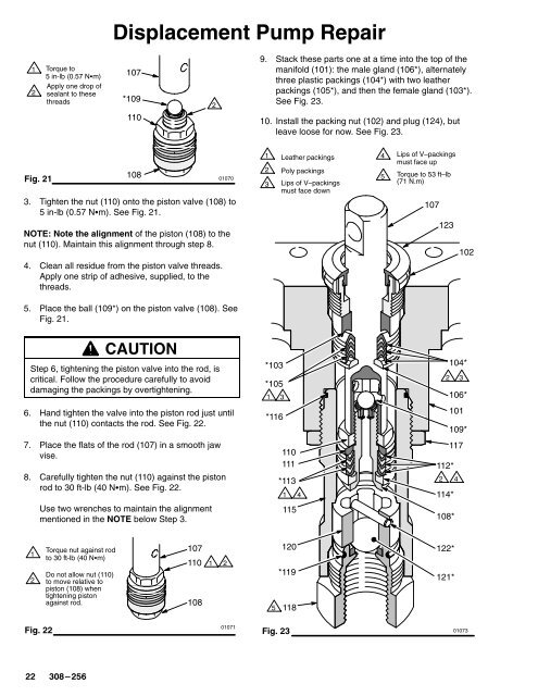
Displacement Pump Repair<br />
<br />
<br />
Torque to<br />
107<br />
Apply one drop of<br />
sealant to these<br />
threads<br />
*109<br />
110<br />
<br />
9. Stack these parts one at a time into the top of the<br />
manifold (101): the male gland (106*), alternately<br />
three plastic packings (104*) with two leather<br />
packings (105*), and then the female gland (103*).<br />
See Fig. 23.<br />
10. Install the packing nut (102) and plug (124), but<br />
leave loose for now. See Fig. 23.<br />
Fig. 21<br />
108<br />
01070<br />
3. Tighten the nut (110) onto the piston valve (108) to<br />
5 in-lb (0.57 Nm). See Fig. 21.<br />
NOTE: Note the alignment of the piston (108) to the<br />
nut (110). Maintain this alignment through step 8.<br />
4. Clean all residue from the piston valve threads.<br />
Apply one strip of adhesive, supplied, to the<br />
threads.<br />
<br />
<br />
<br />
Leather packings<br />
Poly packings<br />
Lips of V–packings<br />
must face down<br />
<br />
<br />
Lips of V–packings<br />
must face up<br />
Torque to 53 ft–lb<br />
(71 N.m)<br />
107<br />
123<br />
102<br />
5. Place the ball (109*) on the piston valve (108). See<br />
Fig. 21.<br />
CAUTION<br />
Step 6, tightening the piston valve into the rod, is<br />
critical. Follow the procedure carefully to avoid<br />
damaging the packings by overtightening.<br />
6. Hand tighten the valve into the piston rod just until<br />
the nut (110) contacts the rod. See Fig. 22.<br />
7. Place the flats of the rod (107) in a smooth jaw<br />
vise.<br />
8. Carefully tighten the nut (110) against the piston<br />
rod to 30 ft-lb (40 Nm). See Fig. 22.<br />
Use two wrenches to maintain the alignment<br />
mentioned in the NOTE below Step 3.<br />
*103<br />
*105<br />
<br />
*116<br />
110<br />
111<br />
*113<br />
<br />
115<br />
104*<br />
<br />
106*<br />
101<br />
109*<br />
117<br />
112*<br />
<br />
114*<br />
108*<br />
<br />
<br />
Torque nut against ro<br />
<br />
Do not allow nut (110)<br />
to move relative to<br />
piston (108) when<br />
tightening piston<br />
against rod.<br />
107<br />
110<br />
108<br />
<br />
<br />
120<br />
*119<br />
118<br />
122*<br />
121*<br />
Fig. 22<br />
01071<br />
Fig. 23<br />
01073


