

Pro 501st Airless Paint Sprayer - Graco Inc.
Pro 501st Airless Paint Sprayer - Graco Inc.
Pro 501st Airless Paint Sprayer - Graco Inc.

You also want an ePaper? Increase the reach of your titles
YUMPU automatically turns print PDFs into web optimized ePapers that Google loves.
WARNING<br />
INJECTION HAZARD<br />
To reduce the risk of serious injury,<br />
whenever you are instructed to relieve<br />
pressure, follow the Pressure Relief<br />
<strong>Pro</strong>cedure on page 9.<br />
Motor Start Board<br />
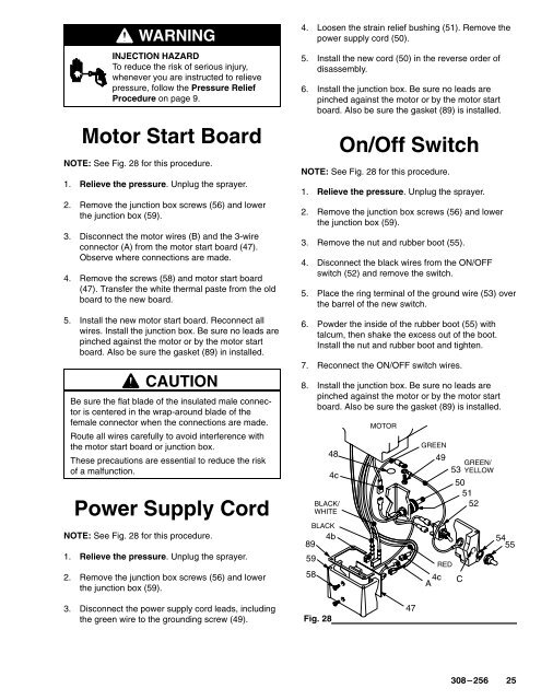
NOTE: See Fig. 28 for this procedure.<br />
1. Relieve the pressure. Unplug the sprayer.<br />
2. Remove the junction box screws (56) and lower<br />
the junction box (59).<br />
3. Disconnect the motor wires (B) and the 3-wire<br />
connector (A) from the motor start board (47).<br />
Observe where connections are made.<br />
4. Remove the screws (58) and motor start board<br />
(47). Transfer the white thermal paste from the old<br />
board to the new board.<br />
5. Install the new motor start board. Reconnect all<br />
wires. Install the junction box. Be sure no leads are<br />
pinched against the motor or by the motor start<br />
board. Also be sure the gasket (89) in installed.<br />
CAUTION<br />
Be sure the flat blade of the insulated male connector<br />
is centered in the wrap-around blade of the<br />
female connector when the connections are made.<br />
Route all wires carefully to avoid interference with<br />
the motor start board or junction box.<br />
These precautions are essential to reduce the risk<br />
of a malfunction.<br />
Power Supply Cord<br />
NOTE: See Fig. 28 for this procedure.<br />
1. Relieve the pressure. Unplug the sprayer.<br />
2. Remove the junction box screws (56) and lower<br />
the junction box (59).<br />
4. Loosen the strain relief bushing (51). Remove the<br />
power supply cord (50).<br />
5. Install the new cord (50) in the reverse order of<br />
disassembly.<br />
6. Install the junction box. Be sure no leads are<br />
pinched against the motor or by the motor start<br />
board. Also be sure the gasket (89) is installed.<br />
On/Off Switch<br />
NOTE: See Fig. 28 for this procedure.<br />
1. Relieve the pressure. Unplug the sprayer.<br />
2. Remove the junction box screws (56) and lower<br />
the junction box (59).<br />
3. Remove the nut and rubber boot (55).<br />
4. Disconnect the black wires from the ON/OFF<br />
switch (52) and remove the switch.<br />
5. Place the ring terminal of the ground wire (53) over<br />
the barrel of the new switch.<br />
6. Powder the inside of the rubber boot (55) with<br />
talcum, then shake the excess out of the boot.<br />
Install the nut and rubber boot and tighten.<br />
7. Reconnect the ON/OFF switch wires.<br />
8. Install the junction box. Be sure no leads are<br />
pinched against the motor or by the motor start<br />
board. Also be sure the gasket (89) is installed.<br />
48<br />
4c<br />
BLACK/<br />
WHITE<br />
BLACK<br />
4b<br />
89<br />
59<br />
58<br />
MOTOR<br />
GREEN<br />
49<br />
GREEN/<br />
53 YELLOW<br />
50<br />
51<br />
52<br />
RED<br />
4c C<br />
A<br />
54 55<br />
3. Disconnect the power supply cord leads, including<br />
the green wire to the grounding screw (49).<br />
Fig. 28<br />
47


