

Pro 501st Airless Paint Sprayer - Graco Inc.
Pro 501st Airless Paint Sprayer - Graco Inc.
Pro 501st Airless Paint Sprayer - Graco Inc.

You also want an ePaper? Increase the reach of your titles
YUMPU automatically turns print PDFs into web optimized ePapers that Google loves.
Drive Housing, Connecting Rod, Crankshaft<br />
WARNING<br />
INJECTION HAZARD<br />
To reduce the risk of serious injury,<br />
whenever you are instructed to relieve<br />
pressure, follow the Pressure Relief<br />
<strong>Pro</strong>cedure on page 9.<br />
NOTE: Inspect parts as they are removed. Replace<br />
parts that are worn or damaged.<br />
1. Remove the displacement pump. See page 20.<br />
2. Remove the pressure control (64). See page 28.<br />
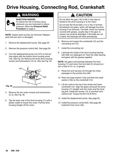
3. Turn the displacement pump rod (107) so the pin<br />
hole aligns with the bottom drive housing screw<br />
(19). See Fig. 29. Remove the three drive housing<br />
screws and lockwashers (19, 6). Also see Fig. 30.<br />
Fig. 29<br />
107<br />
19,6<br />
4. Remove the two motor screws and lockwashers<br />
(5, 6). See Fig. 30.<br />
5. Tap the lower rear of the drive housing (11) with a<br />
plastic mallet to loosen the motor. Pull the drive<br />
housing straight off the motor.<br />
CAUTION<br />
Do not allow the gear (16) to fall; it may stay attached<br />
to the drive housing or to the motor.<br />
Do not lose the thrust balls (11a or 4a) or let them<br />
fall between the gears, which will damage the drive<br />
housing if not removed. The balls, which are heavily<br />
covered with grease, usually stay in the gear recesses,<br />
but could be dislodged. If the balls are not<br />
in place, the bearings will wear prematurely.<br />
6. Remove and inspect the crankshaft (12) and the<br />
connecting rod (15).<br />
7. Install the connecting rod.<br />
8. Lubricate the inside of the drive housing bearing<br />
with SAE non-detergent oil. Pack the roller bearing<br />
and gears with the grease supplied.<br />
NOTE: the gears and bearings between the drive<br />
housing (11) and motor front end bell (C) should contain<br />
a total of 3 fl. oz. of grease.<br />
9. Route the wire harness (A) through the motor<br />
passages to the junction box (59).<br />
10. Place the large washer (12a) and then the small<br />
washer (12b) on the crankshaft (12).<br />
11. Lift the crank to the top of the stroke and insert<br />
crankshaft (12). Align the gears and push the drive<br />
housing (11) straight onto the motor and the locating<br />
pins. Install the screws (19, 5) and their lockwashers<br />
(6). Torque the 80 in-lb (9 Nm).<br />
12. Install the displacement pump. See page 20.<br />
13. Install the pressure control (64). See page 28.<br />
Install the front cover (30).


