

Pro 501st Airless Paint Sprayer - Graco Inc.
Pro 501st Airless Paint Sprayer - Graco Inc.
Pro 501st Airless Paint Sprayer - Graco Inc.

Create successful ePaper yourself
Turn your PDF publications into a flip-book with our unique Google optimized e-Paper software.
Displacement Pump Repair<br />
WARNING<br />
INJECTION HAZARD<br />
To reduce the risk of serious injury,<br />
whenever you are instructed to relieve<br />
pressure, follow the Pressure Relief<br />
<strong>Pro</strong>cedure on page 9.<br />
3. Replace the o-ring (27) if it is worn or damaged.<br />
Reconnect the suction and drain hoses (32, 33).<br />
Install the front cover (13).<br />
4. Tighten the packing nut (102) just enough to stop<br />
leakage, but no tighter. Fill the packing nut/wet-cup<br />
1/4 full with <strong>Graco</strong> TSL. Push the plug (123) into<br />
the wet-cup.<br />
Removing the Pump (See Fig. 17)<br />
1. Flush the pump, if possible. Relieve the pressure.<br />
Stop the pump with the piston rod (107) in its<br />
lowest position, if possible. To lower the piston rod<br />
manually, rotate the motor fan blades.<br />
2. While pulling upward on the suction hose (32),<br />
unscrew the hose from the inlet tube (38). Unscrew<br />
the drain hose (33) from the displacement<br />
pump nipple (36).<br />
13<br />
18<br />
17<br />
NOTE: If repairing only the intake valve assembly, go<br />
to Intake Valve Repair, page 21.<br />
107<br />
20<br />
120<br />
*122<br />
3. Use a screwdriver to push the retaining spring (18)<br />
up and push out the pin (17).<br />
4. Loosen the screws (21). Remove the pump (20).<br />
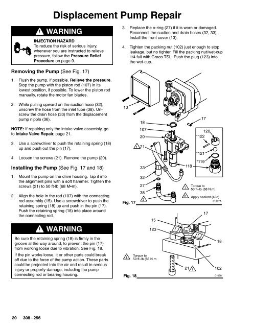
Installing the Pump (See Fig. 17 and 18)<br />
<br />
21<br />
33<br />
118<br />
*121<br />
*119<br />
1. Mount the pump on the drive housing. Tap it into<br />
the alignment pins with a soft hammer. Tighten the<br />
screws (21) to 50 ft-lb (68 Mm).<br />
2. Align the hole in the rod (107) with the connecting<br />
rod assembly (15). Use a screwdriver to push the<br />
retaining spring (18) up and push in the pin (17).<br />
Push the retaining spring (18) into place around<br />
the connecting rod.<br />
Fig. 17<br />
32<br />
27<br />
38<br />
<br />
15<br />
<br />
<br />
Torque to<br />
50 ft–lb (68 N.m)<br />
Apply sealant (42d)<br />
01067A<br />
17<br />
WARNING<br />
123<br />
Be sure the retaining spring (18) is firmly in the<br />
groove al the way around, to prevent the pin (17)<br />
from working loose due to vibration. See Fig. 18.<br />
If the pin works loose, it or other parts could break<br />
off due to the force of the pump action. These parts<br />
could be projected into the air and result in serious<br />
injury or property damage, including the pump<br />
connecting rod or bearing housing.<br />
<br />
Fig. 18<br />
Torque to<br />
50 ft–lb (68 N.m<br />
18<br />
21 <br />
102<br />
01068


