

Pro 501st Airless Paint Sprayer - Graco Inc.
Pro 501st Airless Paint Sprayer - Graco Inc.
Pro 501st Airless Paint Sprayer - Graco Inc.

Create successful ePaper yourself
Turn your PDF publications into a flip-book with our unique Google optimized e-Paper software.
Motor<br />
WARNING<br />
INJECTION HAZARD<br />
To reduce the risk of serious injury,<br />
whenever you are instructed to relieve<br />
pressure, follow the Pressure Relief<br />
<strong>Pro</strong>cedure on page 9.<br />
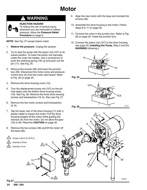
NOTE: See Fig. 27 except where noted.<br />
1. Relieve the pressure. Unplug the sprayer.<br />
2. Try to stop the pump with the piston rod (107) in its<br />
lowest position. To lower the piston rod manually,<br />
rotate the motor fan blades. Use a screwdriver to<br />
push the retaining spring (18) up and push out the<br />
pin (17). See Fig. 25.<br />
3. Remove the screws (56) and lower the junction<br />
box (59). Disconnect the motor wires and pressure<br />
control wire (A) from the motor start board. Refer<br />
to Fig. 28 on page 25.<br />
9. Align the new motor with the base and reinstall the<br />
screws (46).<br />
10. Assemble the drive housing to the motor. Follow<br />
steps 8 to 11 on page 26.<br />
11. Connect the wires in the junction box. Refer to Fig.<br />
28 on page 25. Install the junction box.<br />
12. Connect the piston rod (107) to the drive housing;<br />
see page 20, Installing the Pump, Step 2 and the<br />
WARNING following it.<br />
Fig. 25<br />
15<br />
17<br />
18<br />
4. Remove the drive housing cover (13).<br />
5. Turn the displacement pump rod (107) so the pin<br />
hole aligns with the bottom drive housing screw<br />
(19). See Fig. 26. Remove the three drive housing<br />
screws and lockwashers (19, 6). Also see Fig. 27.<br />
107<br />
19,6<br />
6. Remove the two motor screws and lockwashers<br />
(5, 6).<br />
7. Tap the lower rear of the drive housing (11) with a<br />
plastic mallet to loosen the motor. Pull the drive<br />
housing straight off the motor while guiding the<br />
harness (A) from the motor. Do not allow the gear<br />
(16) to fall. Read the CAUTION on page 26.<br />
8. Remove the two screws (46) and lift the motor off<br />
the base (66).<br />
Fig. 26<br />
01074<br />
16<br />
A<br />
C<br />
B<br />
5<br />
6<br />
4<br />
<br />
Torque to 80 in–lb (9 N.m)<br />
11<br />
<br />
<br />
Quantity of three<br />
Quantity of one<br />
<br />
19<br />
6<br />
13<br />
59<br />
46<br />
<br />
31<br />
56<br />
Fig 27<br />
34<br />
<br />
02839A


