IntuiLink Waveform Editor
IntuiLink Waveform Editor
IntuiLink Waveform Editor

You also want an ePaper? Increase the reach of your titles
YUMPU automatically turns print PDFs into web optimized ePapers that Google loves.
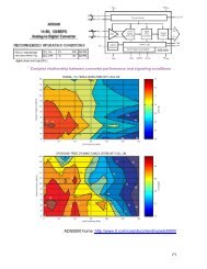
(B) About signal imperfections - 33120A type ARB generator (12-bit, 40 Msa/s, 16K)<br />
Most signal imperfections are easiest to observe in the frequency domain using a<br />
spectrum analyzer. Sampling theory predicts the location and size of spurious signals<br />
resulting from the sampling processes used by DDS generators.<br />
In fact, since DDS generators use a fixed sampling rate (40 MHz for the 33120A), spurious<br />
signals can be removed with a fixed frequency “anti-alias” filter.<br />
A 17 MHz, ninth-order elliptical filter providing a sharp cut-off (in excess of 60 dB attenuation for<br />
signals greater than 19 MHz) is used for sine wave outputs. A 10 MHz, seventh-order Bessel filter<br />
is used for non-sine wave outputs. The Bessel filter provides slower amplitude roll-off for antialias<br />
filtering, but maintains linear phase response to minimize shape distortion for complex<br />
waveshapes. The 33120A automatically selects the appropriate filter when the output function is<br />
selected.<br />
All digital-to-analog converters (DACs), including those used in DDS generators,<br />
produce spurious signals resulting from non-ideal performance. These spurious<br />
signals are harmonically related to the desired output signal. At lower frequencies, the<br />
33120A’s 12-bit waveform DAC produces spurious signals near the -74 dBc level<br />
(decibels below the carrier or output signal). The 33120A uses the complete vertical<br />
resolution (N=1) of the DAC for all internal waveshapes, thus minimizing amplitude<br />
quantization error.<br />
At higher output frequencies, additional DAC errors produce non-harmonic spurious outputs.<br />
These are signals “folded back” or aliased to a frequency within the signal bandwidth. A “perfect”<br />
DAC will also produce a wideband noise floor due to amplitude quantization. The noise floor for a<br />
12-bit DAC will be near the -74 dBc level; this corresponds to a noise density of -147 dBc/Hz for<br />
sine wave outputs 2 from the 33120A.<br />
Another type of waveform error visible in the frequency domain is phase truncation<br />
error. This error results from time quantization of the output waveform. Whenever a<br />
waveshape is described by a finite number of horizontal points (length), it has been<br />
sampled in time (or quantized) causing a phase truncation error. Spurious signals<br />
caused by phase truncation introduce jitter into the output waveform. This may be<br />
regarded as time (and phase) displacement of output zero crossings.<br />
Phase truncation causes phase modulation of the output signal which results in spurious harmonics<br />
(see the equation below). For lower output frequencies, the phase accumulator periodically does<br />
not advance RAM addresses, causing the DAC to deliver the same voltage as recorded on the<br />
previous clock cycle. Therefore, the phase “slips” back by 360 0 / points before continuing to move<br />
forward again. When RAM address increments are the same on each cycle of the output, phase<br />
truncation error (and jitter) are essentially zero. All standard waveshapes in the 33120A are<br />
generated with at least 16,000 waveform points which results in spurious signals below the wideband<br />
noise floor of the DAC.<br />
2 The noise power is normalized to a 1 Hz bandwidth by simply subtracting<br />
6<br />
10 ⋅ log( f / 2) = 10 ⋅ log(40 ⋅10<br />
/ 2) = 73 from the SNR value.<br />
sample<br />
papay@hit.bme.hu <strong>IntuiLink</strong>: <strong>Waveform</strong> <strong>Editor</strong> (ARB generator) 20