

Full Custom IC Desig..
Full Custom IC Desig..
Full Custom IC Desig..

Create successful ePaper yourself
Turn your PDF publications into a flip-book with our unique Google optimized e-Paper software.
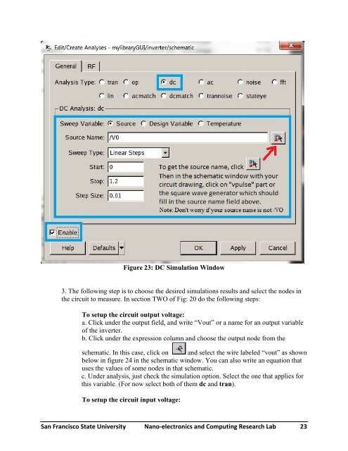
Figure 23: DC Simulation Window<br />
3. The following step is to choose the desired simulations results and select the nodes in<br />
the circuit to measure. In section TWO of Fig: 20 do the following steps:<br />
To setup the circuit output voltage:<br />
a. Click under the output field, and write “Vout” or a name for an output variable<br />
of the inverter.<br />
b. Click under the expression column and choose the output node from the<br />
schematic. In this case, click on and select the wire labeled “vout” as shown<br />
below in figure 24 in the schematic window. You can also write an equation that<br />
uses the values of some nodes in that schematic.<br />
c. Under analysis, just check the simulation option. Select the one that applies for<br />
this variable. (For now select both of them dc and tran).<br />
To setup the circuit input voltage:<br />
San Francisco State University Nano‐electronics and Computing Research Lab 23


