

Full Custom IC Desig..
Full Custom IC Desig..
Full Custom IC Desig..

You also want an ePaper? Increase the reach of your titles
YUMPU automatically turns print PDFs into web optimized ePapers that Google loves.
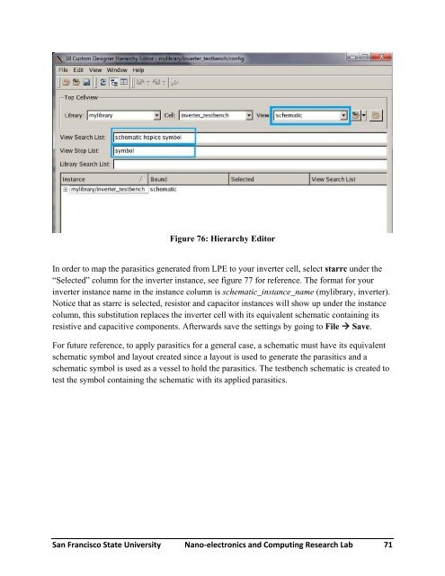
Figure 76: Hierarchy Editor<br />
In order to map the parasitics generated from LPE to your inverter cell, select starrc under the<br />
“Selected” column for the inverter instance, see figure 77 for reference. The format for your<br />
inverter instance name in the instance column is schematic_instance_name (mylibrary, inverter).<br />
Notice that as starrc is selected, resistor and capacitor instances will show up under the instance<br />
column, this substitution replaces the inverter cell with its equivalent schematic containing its<br />
resistive and capacitive components. Afterwards save the settings by going to File Save.<br />
For future reference, to apply parasitics for a general case, a schematic must have its equivalent<br />
schematic symbol and layout created since a layout is used to generate the parasitics and a<br />
schematic symbol is used as a vessel to hold the parasitics. The testbench schematic is created to<br />
test the symbol containing the schematic with its applied parasitics.<br />
San Francisco State University Nano‐electronics and Computing Research Lab 71


