Heatrae Sadia Electromax Installation Guide - Advanced Water
Heatrae Sadia Electromax Installation Guide - Advanced Water
Heatrae Sadia Electromax Installation Guide - Advanced Water

Create successful ePaper yourself
Turn your PDF publications into a flip-book with our unique Google optimized e-Paper software.
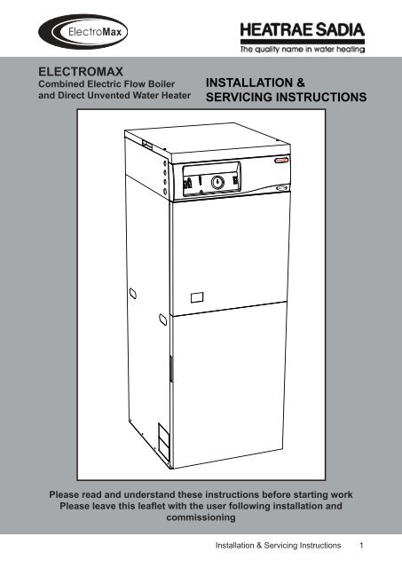
ELECTROMAX<br />
Combined Electric Flow Boiler<br />
and Direct Unvented <strong>Water</strong> Heater<br />
INSTALLATION &<br />
SERVICING INSTRUCTIONS<br />
Please read and understand these instructions before starting work<br />
<br />
commissioning<br />
<strong>Installation</strong> & Servicing Instructions 1
Contents<br />
SECTION<br />
PAGE<br />
SECTION<br />
PAGE<br />
1.0 Introduction<br />
1.1 Important Notes 3<br />
1.2 Basic Operation of the<br />
<strong>Electromax</strong> 3<br />
1.3 Storage, Unpacking and<br />
Handling 4<br />
1.4 Contents Check List 4<br />
2.0 Technical Data 5<br />
3.0 General Requirements<br />
3.1 Location of the <strong>Electromax</strong> 9<br />
3.2 <strong>Water</strong> Supply 9<br />
3.3 Pipework, Fittings and Outlet/<br />
Terminal Fittings 10<br />
3.4 Treatment of the Primary<br />
(Central Heating) Circulating<br />
System 10<br />
3.5 Sealed Primary Systems 11<br />
4.0 <strong>Installation</strong> - General<br />
4.1 Positioning the <strong>Electromax</strong> 12<br />
4.2 Removal of Panels 12<br />
4.3 Cable Entry Positions 13<br />
4.4 Programmable Room<br />
Thermostat 13<br />
5.0 <strong>Installation</strong> - Plumbing<br />
5.1 Pipe Fittings 14<br />
5.2 Cold <strong>Water</strong> Combination<br />
Valve 14<br />
5.3 Secondary Expansion Vessel 14<br />
5.4 Balanced Hot <strong>Water</strong> Supplies 15<br />
5.5 Outlet Pipework 15<br />
5.6 Secondary Circulation 15<br />
5.7 Discharge Pipework 15<br />
5.8 Primary (Central Heating)<br />
Pipework 18<br />
6.0 <strong>Installation</strong> - Electrical<br />
6.1 Important Notes 19<br />
6.2 Off Peak and 24 Hour<br />
Electrical Supply 19<br />
6.3 Boiler Connection (45 Amp) 21<br />
6.4 Programmable Room<br />
Thermostat 21<br />
7.0 Commissioning<br />
7.1 Filling the <strong>Electromax</strong><br />
Cylinder 22<br />
7.2 Filling the Sealed System<br />
Primary Circuit 23<br />
7.3 Check the Operation of the<br />
Safety Valves 23<br />
7.4 Set the Programmable Room<br />
Thermostat 24<br />
7.5 Preliminary Electrical Checks 24<br />
7.6 Check Operation of the<br />
Electric Boiler 24<br />
7.7 Setting the Automatic By-pass<br />
Valve 25<br />
7.8 Check Operation of the<br />
Immersion Heaters 26<br />
7.9 Demonstration to User 26<br />
8.0 Maintenance<br />
8.1 Maintenance Requirements 27<br />
8.2 Check Cylinder <strong>Water</strong> Supply 27<br />
8.3 Descaling Immersion Heaters 27<br />
8.4 Operation of Cylinder Safety<br />
Valves 28<br />
8.5 Operation of Primary System<br />
Safety Valve 28<br />
8.6 Primary System Expansion<br />
Vessel Charge Pressure 28<br />
8.7 Electrical Checks 29<br />
9.0 Fault Finding and Servicing<br />
9.1 Fault Finding 30<br />
9.2 Replacement Parts 35<br />
9.3 Servicing 37<br />
10.0 Guarantee 43<br />
11.0 Spares Stockists 44<br />
2 <strong>Installation</strong> & Servicing Instructions
1.0 Introduction<br />
1.1 Important Notes<br />
The <strong>Electromax</strong> must be installed in<br />
accordance with the manufacturer’s<br />
instructions and all relevant regulations<br />
in force at the time of installation.<br />
This appliance is not intended for use<br />
by persons (including children) with<br />
reduced physical, sensory or mental<br />
capabilities, or lack of knowledge<br />
and experience, unless they have<br />
been given supervision or instruction<br />
concerning the use of the appliance by<br />
a person responsible for their safety.<br />
The <strong>Electromax</strong> Domestic Hot <strong>Water</strong><br />
Cylinder is of the UNVENTED type.<br />
Its installation is subject to Building<br />
Regulation G3 (England and Wales),<br />
Technical Standard P3 (Scotland) or<br />
Building Regulation P5 (Northern Ireland).<br />
<strong>Installation</strong> must be carried out by a<br />
competent person.<br />
The <strong>Electromax</strong> should be installed and<br />
maintained by a competent person. Please<br />
read and understand these instructions<br />
before installing the <strong>Electromax</strong>. Following<br />
installation and commissioning the<br />
operation of the <strong>Electromax</strong>, the central<br />
heating system and associated controls<br />
should be explained to the customer and<br />
these instructions left with them for future<br />
reference.<br />
The <strong>Electromax</strong> electric heating boiler must<br />
be installed into a sealed (pressurized)<br />
primary system. Following installation of<br />
the primary system the system should be<br />
<br />
an inhibitor added.<br />
The <strong>Electromax</strong> Domestic Hot <strong>Water</strong><br />
cylinder is directly heated by means of<br />
electric immersion heaters. The electric<br />
central heating boiler although housed<br />
in the same casing operates completely<br />
independently to the cylinder. It is strongly<br />
recommended that the water heating is<br />
done by means of an Off-Peak electrical<br />
supply.<br />
The use of an Off-Peak tariff that provides<br />
at least three off peak electricity periods,<br />
such as Economy 10, is recommended.<br />
Where possible the central heating<br />
“on” periods should be programmed<br />
to coincide with the off peak electricity<br />
periods available during the day. This<br />
will ensure maximum economy of the<br />
<br />
<strong>Guide</strong>” for information on the off peak<br />
periods available from various electricity<br />
providers.<br />
The <strong>Electromax</strong> does not contain any<br />
substances harmful to health; it does not<br />
contain any asbestos. Small quantities<br />
of adhesives and sealants used in the<br />
manufacture of the product are cured and<br />
present no known hazards.<br />
1.2 Basic operation of the <strong>Electromax</strong><br />
<br />
boiler and direct electrically heated unvented<br />
domestic water heating cylinder.<br />
The domestic hot water is preferentially<br />
heated by an Off Peak electricity supply via an<br />
immersion heater that is specially designed to<br />
heat virtually the complete cylinder capacity.<br />
A “Boost” immersion heater is also provided<br />
to allow a smaller quantity of water to be<br />
heated should the stored hot water be fully<br />
used during the day. The cylinder is factory<br />
insulated with a low heat loss expanded<br />
polyurethane foam.<br />
<strong>Installation</strong> & Servicing Instructions 3
a sealed (pressurized) primary system. It<br />
is suitable for conventional radiator based<br />
<br />
<br />
<br />
sealed system functional and safety controls,<br />
including the circulating pump and primary<br />
expansion vessel. The boiler automatically<br />
responds to lower central heating loads by<br />
reducing (modulating) the boiler output which<br />
saves wasteful on-off cycling. For summer<br />
use the boiler can be switched off on the<br />
<strong>Electromax</strong> control panel, however a “pump<br />
exercise” facility will energise the circulating<br />
pump for a brief period every day to prevent<br />
pump seizure through long periods without<br />
use.<br />
Time and temperature control of the central<br />
heating is by means of a Programmable<br />
Room Thermostat which is supplied loose<br />
with the <strong>Electromax</strong> for remote siting in a<br />
suitable, convenient position.<br />
The necessary cold water mains supply<br />
controls are supplied in a kit for installation<br />
on site in a suitable, convenient position.<br />
<br />
Regulation G3 and <strong>Water</strong> Fittings Regulations<br />
or Byelaws.<br />
1.3 Storage, Unpacking and Handling<br />
The <strong>Electromax</strong> is delivered in protective<br />
expanded polystyrene packaging with<br />
reinforced corner posts. The assembly is<br />
shrunk wrapped in heavy duty polythene. The<br />
<br />
boxed and attached to the main assembly<br />
by 2 polypropylene bands. The assembly<br />
must be stored upright, under cover in dry<br />
conditions.<br />
Units must not be stacked. The packaging<br />
must be removed prior to installation.<br />
Note the weight of the product and the<br />
handling instructions applied to the packaging.<br />
If using a handling device, eg. A sack barrow,<br />
to manually move the <strong>Electromax</strong>, trucking<br />
must be done from the rear to avoid damage<br />
to the outer panels.<br />
The <strong>Electromax</strong> should be lifted and handled<br />
by two persons. Handholds are provided in<br />
the top rear panel, in both side panels and<br />
underneath the <strong>Electromax</strong> assembly to<br />
aid lifting. Stooping should be avoided and<br />
protective clothing worn when necessary.<br />
The packaging is recyclable and should be<br />
disposed of in accordance with environmental<br />
guidelines.<br />
1.4 Contents check list<br />
Within the <strong>Electromax</strong> packaging the following<br />
components are supplied. Please check that<br />
all parts are available before commencing<br />
installation.<br />
<br />
<br />
<br />
<br />
<br />
<br />
<br />
<br />
<br />
<br />
<br />
<strong>Electromax</strong> unit<br />
Cold <strong>Water</strong> Combination Valve<br />
comprising Pressure Reducing Valve,<br />
Strainer, Check Valve and Expansion<br />
Valve<br />
Unvented system Expansion Vessel<br />
(18 litre, pre-charged to 3.5 bar)<br />
Wall mounting bracket for Expansion<br />
Vessel<br />
Programmable Room Thermostat<br />
Immersion heater key spanner<br />
Hose connection adaptor for primary<br />
system drain valve<br />
Set of Cable Entry Glands and blanking<br />
plugs (3 x 20mm, 1 x 25.4mm)<br />
<strong>Installation</strong> Manual<br />
User Instructions<br />
Fitting template<br />
4 <strong>Installation</strong> & Servicing Instructions
2.0 Technical Data<br />
Specification /feature<br />
ElectricBoiler& Prim aryCircu it<br />
E el ctrci al nI put(m ax)<br />
9 kW at240 V<br />
8.3kW at230 V<br />
E el ctrci alsupp yl vo tlage<br />
220 to 240 V<br />
Electricalsupply frequency<br />
50 H z<br />
E el ctrci alsupp yl ratni g<br />
37.5 A m ps at240 V<br />
R C D ratni g<br />
45 A m ps.Trpi ratni g 30m A .<br />
Internalfuse rating (P um p supply)<br />
2 A m ps<br />
P rmi ary system type<br />
S ea el d<br />
Prim arysystem operating pressure (min) 100kP a (1 bar)<br />
Prim arysystem pressure reliefvalve setting 300kP a (3 bar)<br />
Prim ary system E xpansion V essel 12 litre.P re-charged to 100kP a (1 bar)<br />
Prim aryFlow Tem perature R adiatorM odel A djustable from 65 to 80 deg C<br />
Prim aryFlow Tem perature U nderfloorM odel A djustable from 30 to 60degC<br />
A utom atci bypass va vle<br />
S upp eil d tif ted. Adjustable 10 to 50kPa (0.1-0.5bar)differentialpressure<br />
Prim arycirculating pum p S upplied fitted.Grundfos U P S 15-50<br />
A utom atci a ri vent<br />
S upp eil d tif ted.<br />
Tem porary nillif g ol op<br />
S upp eil d tif ted.<br />
DHW<br />
cylinder<br />
OffP eak im mersion heaterinput 3kW at240 V<br />
2.8kW at230 V<br />
Boostim mersion heaterinput 3kW at240 V<br />
2.8kW at230 V<br />
R ated P ressure<br />
600kP a (6 bar).<br />
P ressure reduc ni g va vle<br />
350kP a (3.5 bar). nI tegralw tih C o dl W aterC om b ni atoi n V a vle<br />
E xpans oi n V a vle<br />
600kP a (6 bar). nI tegralw tih C o dl W aterC om b ni atoi n V a vle<br />
D H W E xpans oi n V essel<br />
18 til re.P re-charged to 350kP a (3.5 bar)<br />
Tem perature/Pressure ReliefV alve<br />
90 deg C /1000kPa (10 bar)<br />
Com bined therm ostatand therm alcut-out Therm ostatadjustable 10to 70 deg C .R e-settable cut-out80 deg C<br />
C heck V a vle<br />
nI tegralw tih C o dl W aterC om b ni atoi n V a vle<br />
S tra ni er<br />
nI tegralw tih C o dl W aterC om b ni atoi n V a vle<br />
nI su al toi n<br />
C FC /H C FC expanded po yl urethane.O zone dep el toi n potentai lzero.<br />
GlobalW arm ing potential3.1<br />
Com plete unit<br />
U n ti w e gi ht(em pty)<br />
74 kg<br />
U n ti w e gi ht(uf )ll<br />
256 kg<br />
P ackaged w e gi ht<br />
81 kg<br />
P ackaged dim ensionsH xW xD (mm) Electrom ax unit:1566 x 600 x 650<br />
<strong>Installation</strong> K it:320x315x610<br />
Cylinder Perform ance<br />
Capac tiy<br />
( rtil es)<br />
OffPeak heater3kW Boostheater3kW<br />
Time to heat(mins) Q uan ytit hea et d ht ro'<br />
Thro'45deg C Thro'50deg C 45deg C in60mins<br />
HeatLoss<br />
kW h 2/ 4h<br />
180 180 200 57 litres 1.95<br />
<strong>Installation</strong> & Servicing Instructions 5
Diagram 1 Dimensions<br />
600<br />
TOP<br />
Lifting Points<br />
In Upper Rear<br />
Panel<br />
300<br />
Minimum clearance<br />
over Top Panel for<br />
access<br />
550<br />
LEFT HAND<br />
SIDE<br />
1476<br />
FRONT<br />
Tundish<br />
Viewing<br />
Window<br />
Side Panel Lifting<br />
Points (Mirrored in<br />
Right Hand Side<br />
Panel)<br />
Lifting Points In Base<br />
50<br />
Min.<br />
clearance<br />
either<br />
side<br />
6 <strong>Installation</strong> & Servicing Instructions
Diagram 2 Key Components<br />
Primary System<br />
Expansion Vessel<br />
Air Valve<br />
Primary System<br />
Expansion Vessel<br />
Connection<br />
Primary System<br />
Expansion Vessel<br />
Primary Circulating<br />
Pump<br />
Electric Control Circuitry<br />
(Mounted Behind Fascia)<br />
Automatic Air Vent<br />
Top Panel<br />
User Interface Panel<br />
Electrical Connection<br />
Terminal Blocks<br />
Primary System Pressure<br />
Relief Valve<br />
Temperature / Pressure<br />
Relief Valve<br />
Tundish<br />
Automatic Bypass<br />
Valve<br />
Discharge Pipe<br />
Primary Flow<br />
Isolating Valve<br />
Fascia Panel<br />
Panel Mounted Fuses 3 amp<br />
Boiler Electronic Control<br />
(Under Cover)<br />
Boost Immersion<br />
Heater<br />
Domestic Hot<br />
<strong>Water</strong> Cylinder<br />
(Insulated)<br />
Electric Boiler<br />
Filling Loop<br />
Off Peak Immersion<br />
Heater<br />
Filling Loop<br />
Isolating Valve<br />
Primary Return<br />
Isolating Valve<br />
Primary System<br />
Drain Point<br />
Hot <strong>Water</strong> Outlet<br />
Connection<br />
Cold <strong>Water</strong> Inlet<br />
Filling Loop Connection<br />
Isolating Valve<br />
(Primary Side)<br />
<strong>Installation</strong> & Servicing Instructions 7
Diagram 3 Pump Characteristics<br />
H (m)<br />
5.0<br />
4.0<br />
SPEED<br />
SETTING<br />
SPEED<br />
R.P.M.<br />
INPUT<br />
POWER (W)<br />
FULL LOAD<br />
CURRENT (A)<br />
lll 2300 50 0.23 0.30<br />
ll 2100 45 0.20 0.25<br />
l 1700 35 0.16 0.20<br />
LOCKED ROTOR<br />
CURRENT (A)<br />
3.0<br />
2<br />
3<br />
2.0<br />
1<br />
1.0<br />
0<br />
3<br />
0.2 0.4 0.6 0.8 1.0 1.2 1.4 1.6 1.8 2.0 2.2 2.4 2.6 2.8 3.0 Q (m /h)<br />
Diagram 4 Automatic Bypass Valve Characteristics<br />
1.2<br />
1<br />
Differential Pressure (bar)<br />
0.8<br />
0.6<br />
0.4<br />
0.2<br />
0<br />
0 300 600 900 1200 1500 1800 2100 2400 2700 3000<br />
V (l/h)<br />
8 <strong>Installation</strong> & Servicing Instructions
3.0 General Requirements<br />
3.1 Location of the <strong>Electromax</strong><br />
The <strong>Electromax</strong> must not be sited outside or<br />
in any location where it could be exposed to<br />
the weather. It must be installed in a dry and<br />
frost free environment.<br />
The <strong>Electromax</strong> must be vertically mounted<br />
<br />
the “full” weight of the unit. When full the unit<br />
weighs a total of 256kg.<br />
The location chosen must allow the discharge<br />
pipe from the unvented cylinder safety<br />
valves to be correctly installed. Domestic hot<br />
water pipe runs should be kept as short as<br />
<br />
access must be allowed around the unit to<br />
allow removal of the front and top panels for<br />
servicing and maintenance of the system.<br />
Refer to Diagram 1, page 6 for details of<br />
recommended minimum clearances.<br />
An installation template is supplied with the<br />
unit to aid in location and layout of pipework<br />
connections.<br />
3.2 <strong>Water</strong> supply<br />
Bear in mind that the mains water supply to<br />
the property will be supplying both the hot<br />
and cold water requirements simultaneously.<br />
It is recommended that the maximum<br />
water demand be assessed and the water<br />
supply be checked to ensure this demand<br />
can be satisfactorily met.<br />
NOTE: A high mains water pressure will<br />
<br />
Wherever possible the mains water supply<br />
pipe should be in 22mm OD (copper) or<br />
25mm OD (Blue MDPE). The minimum mains<br />
water supply requirements should be 1.0 bar<br />
<br />
<br />
outlets are used simultaneously, the higher<br />
<br />
the system performance will be.<br />
The <strong>Electromax</strong> unvented cylinder has<br />
an operating pressure of 3.5 bar which is<br />
controlled by the Cold <strong>Water</strong> Combination<br />
Valve. The Cold <strong>Water</strong> Combination Valve<br />
can be connected to a maximum mains<br />
supply pressure of 16 bar. The water supply<br />
must be of wholesome water quality (Fluid<br />
<br />
Regulations 1999).<br />
In some areas of the UK the water supply<br />
may have a high level of natural hardness.<br />
Whilst this is not detrimental to the quality<br />
of the water, in water heating systems the<br />
calcium carbonate which causes the water’s<br />
“hardness” can precipitate onto hot surfaces<br />
and in time adversely affect hot water<br />
performance. If the temporary hardness of<br />
the cold water mains supply exceeds 200mg/l<br />
(check with your <strong>Water</strong> Supply Company) it<br />
is recommended that some form of water<br />
treatment is considered. Any device selected<br />
must be suitable for use in unvented water<br />
heating systems and not unduly affect the<br />
<br />
consult the manufacturer of the device for<br />
details.<br />
<strong>Installation</strong> & Servicing Instructions 9
3.3 Pipework, Fittings and Outlet / Terminal<br />
Fittings<br />
<br />
<br />
systems and have a rated operating<br />
pressure of at least 6 bar. Where plastic<br />
<br />
pressure must be achievable at outlet<br />
temperatures that can be expected within<br />
the hot water distribution pipework. If in<br />
doubt, consult the manufacturer of the<br />
<br />
The <strong>Electromax</strong> unvented cylinder can<br />
be used in conjunction with most types of<br />
<br />
mixer showers or taps to have balanced<br />
pressure hot and cold water supplies, in<br />
these instances the balanced cold water<br />
supply should be teed off the supply to the<br />
<strong>Electromax</strong> immediately after the Cold <strong>Water</strong><br />
Combination Valve (see diagram 5).<br />
Branches to cold outlets where drinking<br />
water may be drawn should be taken<br />
directly from the main supply before the<br />
Cold <strong>Water</strong> Combination Valve to avoid<br />
the possibility of warm expanded water<br />
being drawn from cold taps.<br />
3.4 Treatment of the Primary (Central<br />
Heating) Circulating System<br />
Primary water circulating systems will be<br />
subject to corrosion unless an appropriate<br />
water treatment is applied. Without treatment<br />
<br />
over time as corrosion sludge accumulates<br />
within the system, risking damage to the pump<br />
and valves, system noise and circulation<br />
problems.<br />
Unvented Cylinder<br />
Temperature /<br />
Pressure Relief<br />
Valve<br />
Tundish<br />
Expansion<br />
Vessel<br />
<strong>Electromax</strong> Housing<br />
Unvented System<br />
Primary System<br />
Cold Balanced<br />
Draw Off (to<br />
Mixer Outlets)Cold Draw Off<br />
(to Drinking<br />
<strong>Water</strong> Outlets)<br />
Isolating<br />
Valve<br />
Discharge Pipe<br />
Cylinder Drain<br />
Diagram 5 System Schematic - DHW Cylinder<br />
Expansion Valve<br />
Discharge<br />
Cold <strong>Water</strong><br />
Combination<br />
Valve<br />
Cold <strong>Water</strong><br />
Mains Supply<br />
10 <strong>Installation</strong> & Servicing Instructions
For optimum performance after installation<br />
the <strong>Electromax</strong> boiler and its associated<br />
<br />
accordance with the guidelines given in BS<br />
7593:1992 “Treatment of water in domestic<br />
hot water central heating systems”. This must<br />
involve the use of a proprietary cleanser, such<br />
as GE Betz Sentinel X300 or X400, Fernox<br />
<br />
Follow the manufacturer’s instructions to<br />
ensure correct cleansing of the system.<br />
For long term protection against corrosion<br />
<br />
be dosed with an inhibitor such as GE Betz<br />
Sentinel X100, Fernox MB-1 or Copal, or<br />
Salamander System Inhibitor in accordance<br />
with the guidelines given in BS 7593:1992.<br />
<br />
system will invalidate the appliance<br />
warranty.<br />
3.5 Sealed Primary Systems<br />
The <strong>Electromax</strong> boiler must be installed in a<br />
sealed primary system. All necessary primary<br />
<br />
<strong>Electromax</strong>. The sealed system expansion<br />
vessel fitted has a capacity of 12 litres<br />
which, as a general guide, will be suitable<br />
for a heating system of up to 107 litres. If<br />
in doubt the total primary system volume<br />
must be calculated to determine if additional<br />
expansion volume is required.<br />
The <strong>Electromax</strong> initial primary system cold<br />
<br />
size = 0.11 x the total system volume. The<br />
boiler and pipework within the <strong>Electromax</strong><br />
hold approx. 2 litres of water, therefore<br />
additional system expansion volume will<br />
only be necessary for systems that exceed<br />
107 litres.<br />
The <strong>Electromax</strong> boiler incorporates an<br />
<br />
to the pump housing, see Diagram 6). If any<br />
primary pipework is routed above the level<br />
of the <strong>Electromax</strong> additional air vents must<br />
<br />
return pipes and at any point where air is<br />
likely to collect.<br />
<br />
<strong>Electromax</strong> to allow thermostatic radiator<br />
<br />
Primary System<br />
Expansion Vessel<br />
Primary System<br />
Pressure Relief<br />
Valve<br />
Automatic<br />
Air Vent<br />
Circulating<br />
Pump<br />
<strong>Electromax</strong> Housing<br />
Primary System<br />
Unvented System<br />
Automatic<br />
Bypass Valve<br />
Electric Boiler<br />
Filling Loop<br />
Primary<br />
Flow<br />
Primary<br />
Return<br />
Isolating<br />
Valves - to Radiators<br />
or Undefloor System<br />
Diagram 6 System Schematic - Primary Circuit<br />
Primary System<br />
Drain Valve<br />
<strong>Installation</strong> & Servicing Instructions 11
4.0 <strong>Installation</strong> - General<br />
4.1 Positioning the <strong>Electromax</strong><br />
Decide where the <strong>Electromax</strong> is to be<br />
installed. Reference must be made to the<br />
dimensions of the unit and the minimum<br />
access space requirements (see Diagram 1,<br />
page 6). Consideration must also be taken<br />
of the routing of the pipework to the unit,<br />
provision of the discharge pipe and siting<br />
of any external controls such as the Cold<br />
<strong>Water</strong> Combination Valve and secondary<br />
system Expansion Vessel. Pipework can<br />
be connected from below the unit or from<br />
the left and right hand sides. Knock-outs<br />
are provided in the side panels for side<br />
connections. A template is provided to aid<br />
in positioning the unit and determining the<br />
pipework entry locations.<br />
If using side entry pipework the following<br />
connections are made to the <strong>Electromax</strong><br />
(when viewed from front of unit see Diagram<br />
2, page 7):<br />
Left hand side<br />
<br />
The lower front panel (Panel A on Diagram<br />
7) is secured by spring clips and is removed<br />
<br />
either side of the panel. Once removed, the<br />
two M5 screws securing the lower edge of<br />
the upper front panel must be removed. The<br />
upper front panel (Panel B on Diagram 7)<br />
must then be removed by pulling forward<br />
to disengage it from the remaining spring<br />
clips.<br />
The top panel (Panel C on Diagram 7) is<br />
secured by two screws and spring clips. To<br />
remove, unscrew the two securing screws on<br />
the top panel and then pull upwards using the<br />
<br />
C<br />
Right hand side<br />
Cold water inlet supply, hot outlet supply<br />
Note the weight of the product (see Technical<br />
Specifications) and adopt safe lifting<br />
techniques. A two man lift is recommended.<br />
Hand holds are provided in the left and right<br />
hand side panels, the rear and underside.<br />
If the front panels are removed prior to<br />
<br />
DO NOT lift using the exposed pipework<br />
assembly.<br />
4.2 Removal of Panels<br />
B<br />
A<br />
Refer to Diagram 7. For installation and<br />
commissioning the front and top panels must<br />
be removed. The lower front panel must be<br />
removed before the upper front panel.<br />
<br />
12 <strong>Installation</strong> & Servicing Instructions
4.3 Cable Entry Positions<br />
The electrical supply cables can be routed to<br />
enter the unit from the left or right hand side<br />
(see Diagram 8). There are four cable entry<br />
holes in each upper side panel; one 25mm<br />
diameter and three 20mm diameter. The<br />
accessory kit contains a set of cable glands<br />
<br />
<br />
the side selected for cable entry and secured<br />
in place using the lock nuts supplied. The<br />
remaining four cable entry holes not used<br />
should be blanked off using the appropriate<br />
blanking plugs supplied.<br />
The cable glands must be used to secure the<br />
<br />
to do so can result in the cables straining<br />
internal electrical connections and possible<br />
electrical failure as a result. Failure due to<br />
inadequate cable securing will not be covered<br />
by the warranty.<br />
4.4 Programmable Room Thermostat<br />
The <strong>Electromax</strong> is supplied with a Danfoss<br />
TP5000 Programmable Room Thermostat.<br />
This is supplied in the accessory kit supplied<br />
with your unit. Follow the installation<br />
instructions provided with the Programmable<br />
Room Thermostat for correct siting and<br />
mounting of the unit. If the radiators are to<br />
<br />
(TRV’s) the room where the Programmable<br />
Room Thermostat is located must not have<br />
a TRV fitted in compliance with Building<br />
Regulation Part L.<br />
Diagram Programmable Room Thermostat<br />
Diagram 8 Cable Entry Positions<br />
Top<br />
Panel<br />
20mm<br />
Front<br />
Panel<br />
25mm<br />
Right hand cable<br />
entry holes shown.<br />
Left hand holes<br />
are mirrored in left<br />
hand panel.<br />
<strong>Installation</strong> & Servicing Instructions 13
5.0 <strong>Installation</strong> - Plumbing<br />
<br />
Diagram 10 Cold <strong>Water</strong> Combination Valve<br />
Pipe connections to the <strong>Electromax</strong> must be<br />
<br />
Solder connections directly to the unit must<br />
not be made as the heat may damage the<br />
insulation materials used. Damage caused<br />
<br />
proximity to the unit will not be covered by<br />
the warranty. Solder connections may be<br />
used elsewhere in the system away from the<br />
<br />
<br />
residue is removed following installation.<br />
5.2 Cold <strong>Water</strong> Combination Valve<br />
EXPANSION VALVE<br />
COLD MAINS<br />
CONNECTION<br />
(22mm)<br />
PRESSURE<br />
REDUCING<br />
VALVE<br />
HOUSING<br />
EXPANSION VALVE<br />
OUTLET (15mm)<br />
OUTLET<br />
CONNECTION<br />
(22mm)<br />
The Cold <strong>Water</strong> Combination Valve can be<br />
connected anywhere on the cold water mains<br />
supply prior to the <strong>Electromax</strong> unit, however<br />
it must be possible to connect the secondary<br />
system Expansion Vessel between this<br />
valve and the cold inlet connection of the<br />
unit. Whilst it is often more convenient to<br />
do so, there is no requirement to site the<br />
valve close to the unit, it can be located at<br />
a point remote from the unit if this is more<br />
convenient. However, ensure the discharge<br />
from the Expansion Valve (see Diagram 10)<br />
can be correctly installed. The Expansion<br />
Valve connection must not be used for any<br />
other purpose.<br />
The Cold <strong>Water</strong> Combination Valve is installed<br />
as a complete one-piece unit. The valve<br />
incorporates an Isolating Valve, a Pressure<br />
Reducer, a Strainer, an Expansion Valve<br />
and a single Check Valve. The valve can be<br />
<br />
however, ensure the valve is installed with<br />
<br />
side of the brass body) pointing towards the<br />
<strong>Electromax</strong> unit.<br />
PRESSURE<br />
REDUCING<br />
VALVE<br />
CARTRIDGE (3.5 bar)<br />
5.3 Secondary Expansion Vessel<br />
The Secondary (DHW) Expansion Vessel is<br />
<br />
to the cold water supply to the <strong>Electromax</strong><br />
to accommodate any water expansion that<br />
results from heating the water inside the<br />
<br />
between the Cold <strong>Water</strong> Combination Valve<br />
and the cold inlet of the <strong>Electromax</strong> cylinder<br />
(see Diagram 5, page 10).<br />
The Expansion Vessel must be adequately<br />
supported, a wall mounting bracket is<br />
supplied for this purpose. The location of the<br />
Expansion Vessel should allow access for<br />
maintenance. This will entail access to the<br />
air valve on top of the unit to check and, if<br />
necessary, re-charge the vessel pre-charge<br />
pressure. The vessel pre-charge pressure<br />
is 3.5 bar.<br />
14 <strong>Installation</strong> & Servicing Instructions
5.4 Balanced Cold <strong>Water</strong> Supplies<br />
It is advantageous in many mixer showers<br />
or taps to have balanced pressure hot and<br />
cold water supplies, in these instances the<br />
balanced cold water supply should be teed<br />
off the supply to the <strong>Electromax</strong> immediately<br />
after the Cold <strong>Water</strong> Combination Valve (see<br />
diagram 5, page 10).<br />
Branches to cold outlets where drinking<br />
water may be drawn should be taken<br />
directly from the main supply before the<br />
Cold <strong>Water</strong> Combination Valve to avoid<br />
the possibility of warm expanded water<br />
being drawn from cold taps.<br />
5.5 Outlet Pipework<br />
The pipework from the <strong>Electromax</strong> to the<br />
<br />
with short runs of 15mm pipe to showers<br />
and basins. Small bore pipe can be used to<br />
suit some taps, but runs should be kept as<br />
short as possible. Pipe sizes may vary due<br />
to system design.<br />
5.6 Secondary Circulation<br />
Secondary circulation is not recommended<br />
for the <strong>Electromax</strong> as it is intended for<br />
Off-Peak electrical operation. During other<br />
periods the electricity supply is interrupted<br />
to the immersion heaters so no reheating<br />
will take place. Circulating the stored water<br />
would gradually cool it to an unacceptable<br />
temperature.<br />
<br />
It is a requirement of Building Regulations<br />
that any discharge from an unvented system<br />
should be visible and safely conveyed away<br />
from the system without danger to persons in<br />
or about the building where it is installed. The<br />
<br />
with the requirements and guidance notes of<br />
Building Regulations. Building Regulation G3<br />
Requirements and Guidance section 3.9 are<br />
reproduced in the following sections.<br />
Information Sheet No.33 available from<br />
the British Board of Agrement gives further<br />
advice on discharge pipe installation. For<br />
discharge pipe arrangements not covered<br />
by G3 Guidance or BBA Info sheet No. 33<br />
advice should be sought from either your<br />
local Building Control Officer or <strong>Heatrae</strong><br />
<br />
to the <strong>Electromax</strong> will convey any discharge<br />
from the unvented cylinder Temperature<br />
and Pressure Relief Valve and the sealed<br />
system Pressure Relief Valve. A discharge<br />
pipe will also be required from the Expansion<br />
<br />
Valve. Where practical this can be teed into<br />
the discharge pipe from the <strong>Electromax</strong>. It<br />
is recommended that an additional tundish<br />
<br />
early indication of operation of the Expansion<br />
Valve.<br />
In some instances it may be possible to<br />
discharge into an internal waste system and<br />
soil stack. To do this a self sealing waste<br />
<br />
after the tundish to prevent foul odours or<br />
back-pressurisation from the waste system<br />
entering the building via the tundish. In these<br />
systems it is essential that the tundish is<br />
<br />
of discharge will not be visible. Consult<br />
the manufacturer’s recommendations with<br />
<br />
waste and soil stack materials selection. It<br />
will also be necessary to get dispensation<br />
<br />
discharge in this manner. Discharges from<br />
an unvented system can be up to 95 o C for<br />
several minutes, ensure any waste or soil<br />
pipe connected to the discharge can<br />
safely accept these conditions.<br />
G3 REQUIREMENT<br />
“…there shall be precautions…to ensure that<br />
the hot water discharged from safety devices<br />
is safely conveyed to where it is visible but<br />
will not cause danger to persons in or about<br />
the building.”<br />
<strong>Installation</strong> & Servicing Instructions 15
<strong>Water</strong> may drip from the discharge pipe of<br />
the pressure-relief device and that this pipe<br />
must be left open to the atmosphere.<br />
The pressure-relief device is to be operated<br />
regularly to remove lime deposits and to<br />
verify that it is not blocked.<br />
The discharge pipe connected to the<br />
pressure relief device is to be installed in a<br />
continuously downward direction and in a<br />
frost free environment<br />
<br />
The discharge pipe (D1) (see Diagram<br />
11, page 17) from the vessel up to and<br />
including the tundish is generally supplied<br />
by the manufacturer of the hot water storage<br />
system. Where otherwise, the installation<br />
should include the discharge pipe(s) (D1)<br />
from the safety device(s). In either case<br />
the tundish should be vertical, located in<br />
the same space as the unvented hot water<br />
<br />
possible and within 500mm of the safety<br />
device e.g. the temperature relief valve.<br />
The discharge pipe (D2) from the tundish<br />
should terminate in a safe place where there<br />
is no risk to persons in the vicinity of the<br />
discharge, preferably be of metal and:<br />
a. be at least one pipe size larger than the<br />
nominal outlet size of the safety device unless<br />
its total equivalent hydraulic resistance<br />
exceeds that of a straight pipe 9m long<br />
i.e. discharge pipes between 9m and 18m<br />
equivalent resistance length should be two<br />
pipe sizes larger, and so on. Bends must<br />
<br />
resistance. Refer to Diagram 11, Table 1 and<br />
the worked example.<br />
An alternative approach for sizing discharge<br />
pipes would be to follow BS6700:1987<br />
<br />
<br />
<br />
Appendix E, section E2 and Table<br />
21.<br />
b. have a vertical section of pipe at least<br />
300mm long below the tundish before any<br />
elbows or bends in the pipework.<br />
c. be installed with a continuous fall.<br />
d. have discharges visible at both the tundish<br />
but where this<br />
<br />
should be clear visibility at one or other of<br />
these locations.<br />
Examples of acceptable discharge<br />
arrangements are:<br />
<br />
the water seal in a trapped gully.<br />
ii. Downward discharges at low level; i.e.<br />
up to 100mm above external surfaces such<br />
as car parks, hard standings, grassed areas<br />
etc. are acceptable providing that where<br />
children may play or otherwise come into<br />
contact with discharges a wire cage or similar<br />
guard is positioned to prevent contact, whilst<br />
maintaining visibility.<br />
iii. Discharges at high level; e.g. into<br />
a metal hopper and metal down pipe with<br />
the end of the discharge pipe clearly visible<br />
(tundish visible or not) or onto a roof capable<br />
of withstanding high temperature discharges<br />
of water and 3m from any plastics guttering<br />
system that would collect such discharges<br />
(tundish visible).<br />
iv. Where a single pipe serves a number<br />
of discharges, such as in blocks of flats,<br />
the number served should be limited to not<br />
more than 6 systems so that any installation<br />
discharging can be traced reasonably easily.<br />
The single common discharge pipe should<br />
be at least one pipe size larger than the<br />
largest individual discharge pipe (D2) to be<br />
connected. If unvented hot water storage<br />
systems are installed where discharges from<br />
safety devices may not be apparent i.e. in<br />
<br />
people, consideration should be given to<br />
the installation of an electronically operated<br />
device to warn when discharge takes place.<br />
Note: The discharge will consist of scalding<br />
<br />
metallic rainwater goods may be damaged by<br />
such discharges.<br />
16 <strong>Installation</strong> & Servicing Instructions
Worked example of discharge pipe<br />
sizing<br />
The example below is for a G1/2 temperature<br />
relief valve with a discharge pipe (D2) having<br />
4 No. elbows and length of 7m from the<br />
tundish to the point of discharge.<br />
From Table 1:<br />
Maximum resistance allowed for a straight<br />
length of 22mm copper discharge pipe<br />
(D2) from a G1/2 temperature relief valve<br />
is 9.0m.<br />
Table 1 Sizing of Copper Discharge<br />
Pipes (D2) for Common T&P Relief Valve<br />
Sizes<br />
Valve outlet size<br />
Minimum size of<br />
discharge pipe D1<br />
G1/2 15mm<br />
G3/4 22mm<br />
G1<br />
28mm<br />
Minimum size of<br />
discharge pipe D2<br />
from tundish<br />
22mm<br />
28mm<br />
35mm<br />
28mm<br />
35mm<br />
42mm<br />
35mm<br />
42mm<br />
54mm<br />
Subtract the resistance allowed for 4 No.<br />
22mm elbows at 0.8m each = 3.2m<br />
Therefore the permitted length equates to:<br />
5.8m<br />
5.8m is less than the actual length of 7m<br />
therefore calculate the next largest size.<br />
Maximum resistance allowed for a straight<br />
length of 28mm pipe (D2) from a G1/2<br />
temperature relief valve equates to 18m.<br />
Subtract the resistance of 4 No. 28mm<br />
elbows at 1.0m each = 4.0m<br />
Therefore the maximum permitted length<br />
equates to 14.0m<br />
As the actual length is 7m, a 28mm (D2)<br />
copper pipe will be satisfactory.<br />
Maximum<br />
resistance<br />
allowed,<br />
expressed as a<br />
length of straight<br />
pipe (I.e. no<br />
elbows or bends)<br />
up to 9m<br />
up to 18m<br />
up to 27m<br />
up to 9m<br />
up to 18m<br />
up to 27m<br />
up to 9m<br />
up to 18m<br />
up to 27m<br />
Resistance<br />
created by each<br />
elbow or bend<br />
0.8m<br />
1.0m<br />
1.4m<br />
1.0m<br />
1.4m<br />
1.7m<br />
1.4m<br />
1.7m<br />
2.3m<br />
Safety device<br />
(e.g. Temperature<br />
relief valve)<br />
Metal discharge pipe (D1) from<br />
Temperature relief valve to tundish<br />
500mm maximum<br />
Tundish<br />
300mm<br />
minimum<br />
Diagram 11<br />
Schematic Discharge<br />
Pipe Arrangement<br />
Discharge pipe (D2) from tundish,<br />
with continuous fall. See Building<br />
Regulation G3 section 3.9d i-iv,<br />
Table 4 and worked example<br />
Discharge below<br />
fixed grating<br />
(Building Regulation<br />
G3 section 3.9d gives<br />
alternative points<br />
of discharge)<br />
Fixed grating<br />
Trapped<br />
gully<br />
<strong>Installation</strong> & Servicing Instructions 17
5.8 Primary (Central Heating) Pipework<br />
<br />
and return must be in 22mm o/dia. pipe.<br />
<br />
<br />
to enable the <strong>Electromax</strong> boiler to be isolated<br />
from the primary circuit for maintenance and<br />
servicing. Connections to the isolating valves<br />
are 22mm compression.<br />
Conventional radiator based central heating<br />
design considerations should be made<br />
in selecting the radiators and circulating<br />
pipework sizes. The maximum output from<br />
the <strong>Electromax</strong> boiler is 9kW, ensure the<br />
radiator load does not exceed this. NOTE:<br />
The <strong>Electromax</strong> boiler is dedicated to the<br />
space heating only, the domestic hot water<br />
is heated by separate immersion heaters,<br />
so there is no requirement to allow a hot<br />
water loading factor in designing the primary<br />
system.<br />
<br />
<br />
following installation.<br />
A filling loop is provided within the<br />
<strong>Electromax</strong> casing to fill the primary<br />
circuit directly from the cold water supply.<br />
When the system is full and correctly<br />
<br />
loop should be disconnected from the<br />
primary circuit.<br />
Diagram 12<br />
Primary Connections<br />
Primary Flow<br />
Isolating Valve<br />
Filling Loop<br />
Flexible<br />
Connection<br />
<br />
<br />
Primary Return<br />
Isolating Valve<br />
Hot <strong>Water</strong><br />
Outlet<br />
Connection<br />
Filling Loop<br />
Isolating Valve<br />
(Primary Side)<br />
Filling Loop<br />
Isolating Valve<br />
(Cold <strong>Water</strong> Side)<br />
Cold <strong>Water</strong><br />
Inlet Connection<br />
18 <strong>Installation</strong> & Servicing Instructions
6.0 <strong>Installation</strong> - Electrical<br />
6.1 Important Notes<br />
All wiring must be carried out in accordance<br />
with the current IEE Wiring Regulations.<br />
The <strong>Electromax</strong> electrical installation must<br />
be carried out by a competent person in<br />
accordance with any relevant regulations<br />
in force at the time of installation and the<br />
requirements of these instructions to ensure<br />
correct operation.<br />
The main incoming electrical supply to the<br />
<br />
and voltage for the <strong>Electromax</strong> and any other<br />
electrical requirements for the property.<br />
<br />
double pole RCD with a trip sensitivity of<br />
30mA capable of breaking the full load<br />
current to BS EN 61008:1994.<br />
A correctly rated MCB must be used in<br />
the supply to the <strong>Electromax</strong> boiler and<br />
immersion heaters. The MCB to the boiler<br />
must be rated at 45A. The MCB to each<br />
immersion heater must be rated at 16A. It<br />
<br />
between the 45A MCB and other MCB’s in the<br />
consumer unit to provide ventilation, check<br />
with the MCB manufacturer.<br />
Each circuit must incorporate an isolating<br />
switch which must have a minimum contact<br />
separation of at least 3mm in all poles.<br />
3 amp protection has been provided for the<br />
thermostat ‘L’ and the pump ‘L’. The fuses<br />
are located in the control assembly.<br />
6.2 Off-Peak and 24 hour Electrical<br />
Supply<br />
To obtain optimum performance and lowest<br />
running costs from your <strong>Electromax</strong> unit it<br />
should be connected to an Off-Peak electrical<br />
supply. The “Economy 10” tariff, which is<br />
available from most major electricity suppliers,<br />
is recommended. Table 2 shows the suppliers<br />
that offer “Economy 10” and the times that “off<br />
peak” electricity is supplied. Other Off-Peak<br />
tariffs may be suitable, consult the <strong>Heatrae</strong><br />
<br />
supplier for further advice.<br />
With an Off-Peak electrical supply there will<br />
be two sets of electrical outputs from the<br />
consumer unit or two separate consumer<br />
units. One will supply the circuits that have a<br />
dedicated off peak use (such as night storage<br />
heaters or off peak water heater), the other<br />
will provide a 24 hour supply to circuits in<br />
use throughout the day (such as lighting,<br />
sockets, etc.).<br />
ECONOMY 10 PROVIDERS<br />
Electricity Supplier Off-Peak Times GMT or Clock<br />
Midlands midnight - 5.00am 1.00 - 4.00pm 8.00 - 10.00pm GMT<br />
Norweb midnight - 5.00am 1.00 - 4.00pm 8.00 - 10.00pm GMT<br />
Southern midnight - 5.00am 1.00 - 4.00pm 8.00 - 10.00pm GMT<br />
South Wales midnight - 5.00am 1.00 - 4.00pm 8.00 - 10.00pm GMT<br />
South Western midnight - 5.00am 1.00 - 4.00pm 8.00 - 10.00pm GMT<br />
Yorkshire midnight - 5.00am 1.00 - 4.00pm 8.00 - 10.00pm GMT<br />
Scottish Hydro 4.30 - 7.30am 1.00 - 4.00pm 8.30 - 12.30pm Clock<br />
Manweb 4.30 - 7.30am 1.00 - 4.00pm 8.30 - 12.30pm Clock<br />
Table 2 Economy 10 Providers<br />
<strong>Installation</strong> & Servicing Instructions 19
Off Peak supply connection<br />
A suitable electrical connection must be taken<br />
from the Off Peak supply to the <strong>Electromax</strong><br />
terminal block. The supply cable should<br />
be 1.5mm 2 cross sectional area 3 core<br />
HOFR sheathed cable and must be routed<br />
into the <strong>Electromax</strong> via one of the 20mm<br />
<br />
3.3, page 10). The Live (Brown) conductor<br />
should be connected to the termination<br />
marked “OFF PEAK SUPPLY L”; the Neutral<br />
(Blue) conductor should be connected to the<br />
termination marked “OFF PEAK NEUTRAL<br />
N”; the Earth (Green/Yellow) conductor<br />
should be connected to one of the terminations<br />
marked “EARTH CONNECTIONS “. See<br />
section 6.1, page 19 for MCB and isolation<br />
requirements.<br />
24 Hour supply connection (NB NOT Boiler<br />
connection)<br />
A suitable electrical connection must be taken<br />
from the 24 Hour supply to the <strong>Electromax</strong><br />
terminal block. The supply cable should<br />
be 1.5mm 2 cross sectional area 3 core<br />
HOFR sheathed cable and must be routed<br />
into the <strong>Electromax</strong> via one of the 20mm<br />
<br />
3.3, page 10). The Live (Brown) conductor<br />
should be connected to the termination<br />
marked “24 HOUR SUPPLY L”; the Neutral<br />
(Blue) conductor should be connected to the<br />
termination marked “ 24 HOUR NEUTRAL<br />
N”; the Earth (Green/Yellow) conductor should<br />
be connected to one of the terminations<br />
marked “EARTH CONNECTIONS “. See<br />
section 6.1, page 19 for MCB and isolation<br />
requirements.<br />
Pum p Fuse (3 Am p) Thermostat‘L’Fuse (3 Am p)<br />
Diagram 13 Electrical Supply Connection Block<br />
20 <strong>Installation</strong> & Servicing Instructions
6.3 Boiler Connection (45 Amp)<br />
The <strong>Electromax</strong> boiler has a rated maximum<br />
output of 9kW at 240V ~ . The supply cable<br />
must therefore be separate and dedicated<br />
to the boiler. The supply cable should be a<br />
minimum of 6mm 2 cross sectional area, check<br />
the IEE Wiring Regulations for correct cable<br />
sizing). It must be routed into the <strong>Electromax</strong><br />
<br />
(see section 3.3, page 10). The Live (Brown)<br />
conductor should be connected to the<br />
termination marked “L 45 AMP SUPPLY”;<br />
the Neutral (Blue) conductor should be<br />
connected to the termination marked “N<br />
45AMP SUPPLY”; the Earth (Green/Yellow)<br />
conductor should be connected to the<br />
termination marked “ 45 AMP SUPPLY “.<br />
Where “twin and earth” cable is being used<br />
the bare earth conductor should be sleeved<br />
with suitable Green / Yellow earth cable<br />
sleeving. See section 6.1, page 19 for MCB<br />
and isolation requirements.<br />
6.4 Programmable Room Thermostat<br />
Connection<br />
<br />
the Programmable Room Thermostat and<br />
Diagram 14 (Schematic Wiring Diagram).<br />
Connection to the <strong>Electromax</strong> should be<br />
with 2 core cable of 0.5mm 2 to 1.0mm 2 cross<br />
sectional area suitable for a 240V supply,<br />
bell wire MUST NOT be used. The cable<br />
must be routed into the <strong>Electromax</strong> via one<br />
<br />
(see section 3.3, page 10). One conductor<br />
should be connected to the termination<br />
marked “TO ROOM THERMOSTAT L”;<br />
the other conductor should be connected<br />
to the termination marked “FROM ROOM<br />
THERMOSTAT RUN”.<br />
Please note that the terminations on the<br />
Programmable Room Thermostat marked<br />
“B COM” and “C N/O” should be used.<br />
Connection to terminal “A N/C” will result in<br />
incorrect operation of the <strong>Electromax</strong> boiler.<br />
The clock function of the Programmable<br />
Room Thermostat is battery operated (2 x AA/<br />
MN1500/LR alkaline batteries supplied).<br />
BOOST (TOP)<br />
IMMERSION<br />
HEATER<br />
OFF PEAK (LOWER)<br />
IMMERSION<br />
HEATER<br />
BOOST HEATER<br />
ON<br />
INDICATOR<br />
NEON<br />
A B<br />
A B<br />
ALL EARTH POINTS MUST BE<br />
LINKED BACK TO THE CONTROLS<br />
ASSEMBLY EARTH TERMINATIONS<br />
DHW ON<br />
SWITCH<br />
0.47uFX2<br />
CAPACITOR<br />
1 2 3 1 2 3 1 2 3<br />
NN<br />
TIMER 1 TIMER 2 RELAY 1 RELAY 2<br />
15 16 18 A1 B1 A2 15 16 18 A1 B1A2 A1A2 21 24 A1A2<br />
11 14<br />
FASCIA<br />
CONTROLS<br />
ASSEMBLY<br />
PUMP<br />
BOOST ON<br />
SWITCH<br />
CH ON<br />
SWITCH<br />
3A<br />
3A<br />
N<br />
L<br />
TERMINAL<br />
BLOCK<br />
OFF 24<br />
PEAK HOUR<br />
N N<br />
SPARE<br />
OFF 24<br />
PEAK HOUR<br />
L L<br />
SPARE<br />
ROOM ROOM<br />
STAT STAT<br />
L R<br />
N<br />
L<br />
NC N N L<br />
N<br />
L<br />
CONTROL PUMP CONN 5<br />
Diagram 14<br />
Schematic Wiring<br />
Diagram<br />
OFF PEAK<br />
SUPPLY<br />
16AMP<br />
24 HOUR<br />
SUPPLY<br />
16AMP<br />
A B C<br />
N/C COM<br />
N/O<br />
ELECTRIC<br />
BOILER<br />
SUPPLY<br />
45AMP<br />
PROGRAMMABLE<br />
ROOM<br />
THERMOSTAT<br />
(SUPPLIED)<br />
ELECTRIC BOILER<br />
CONTROL PCB<br />
<strong>Installation</strong> & Servicing Instructions 21
IMPORTANT : DO NOT SWITCH ON<br />
THE ELECTRICAL SUPPLIES TO THE<br />
ELECTROMAX UNTIL THE CYLINDER<br />
AND PRIMARY CIRCUIT HAVE BEEN<br />
CORRECTLY FILLED WITH WATER<br />
<br />
a. Check that all connections to the<br />
<strong>Electromax</strong> are tight.<br />
b. Open a hot tap furthest from the<br />
<strong>Electromax</strong>.<br />
c. Check the Primary System Filling<br />
Loop isolating valves are closed (see<br />
Diagram 15).<br />
d. Open the cold water supply isolating<br />
valve and allow the <strong>Electromax</strong><br />
cylinder to fill. When water issues<br />
from the tap, allow to run for a few<br />
<br />
any residue, dirt or swarf, then close<br />
tap.<br />
Diagram 15<br />
Connections and<br />
Filling Points<br />
Primary Flow<br />
Isolating Valve<br />
e. Open successive hot taps and any<br />
cold outlet supplied by a balanced<br />
take off to purge any air from the<br />
system.<br />
f. Check all connections (including<br />
immersion heater connections) for<br />
leaks and rectify as necessary.<br />
g. The strainer housed within the Cold<br />
<strong>Water</strong> Combination Valve should be<br />
cleaned to remove any debris that<br />
<br />
main supply pipe. Refer to section 8.2,<br />
page 27 for instructions on how to do<br />
this.<br />
Filling Loop<br />
Flexible<br />
Connection<br />
<br />
<br />
Primary Return<br />
Isolating Valve<br />
Hot <strong>Water</strong><br />
Outlet<br />
Connection<br />
Filling Loop<br />
Isolating valve<br />
(Primary Side)<br />
Filling Loop<br />
Isolating valve<br />
Cold <strong>Water</strong><br />
Inlet Connection<br />
22 <strong>Installation</strong> & Servicing Instructions
Circuit<br />
<br />
in accordance with BS 7593 and the<br />
manufacturer’s instructions supplied<br />
<br />
b. Connect the Primary Filling Loop and<br />
tighten connections (see Diagram<br />
15).<br />
c. Check all radiator valves are in the<br />
open position.<br />
d. Open the Filling Loop isolating valves<br />
<br />
the pressure gauge on the fascia of<br />
the <strong>Electromax</strong> reads approx. 2.0<br />
bar.<br />
e. Purge air from all radiators and air<br />
vent points in the primary system.<br />
f. Check the primary system pressure.<br />
This should be between 1.0 and<br />
1.5 bar. If lower, open Filling Loop<br />
isolating valves until gauge reads<br />
approx. 2.0 bar. Repeat air purging<br />
operation. This sequence may need<br />
to be repeated several times to ensure<br />
all air is purged from the system.<br />
g. Check primary system for leaks and<br />
rectify as necessary.<br />
h. When the pressure gauge remains<br />
steady at between 1.0 and 1.5 bar<br />
ensure both Filling Loop isolating<br />
valves are closed and remove Filling<br />
<br />
system connection point.<br />
<br />
Valves<br />
a. Slowly manually open, for a few<br />
seconds, the Temperature and Pressure<br />
Relief Valve on the <strong>Electromax</strong> (see<br />
Diagram 16). Check water discharged<br />
runs freely away through the tundish<br />
and discharge pipework. Close valve,<br />
<br />
reseats correctly.<br />
Primary<br />
Flow Pipe<br />
Temperature /<br />
Pressure<br />
Relief Valve<br />
Tundish<br />
Diagram 16 Safety Valve<br />
and Tundish Positions<br />
Primary Pressure<br />
Relief Valve<br />
Discharge<br />
Pipe<br />
b. Repeat the above steps for the<br />
Expansion Valve situated on the<br />
Cold water Combination Valve (see<br />
Diagram 17)<br />
EXPANSION VALVE<br />
COLD MAINS<br />
CONNECTION<br />
(22mm)<br />
PRESSURE<br />
REDUCING<br />
VALVE<br />
HOUSING<br />
<br />
<strong>Water</strong> Combination<br />
Valve<br />
EXPANSION VALVE<br />
OUTLET (15mm)<br />
OUTLET<br />
CONNECTION<br />
(22mm)<br />
PRESSURE<br />
REDUCING<br />
VALVE<br />
CARTRIDGE (3.5 bar)<br />
c. Repeat the above steps for the<br />
Primary System Pressure Relief Valve<br />
on the <strong>Electromax</strong> (see Diagram 16).<br />
After this operation check that the<br />
primary system pressure has not<br />
dropped below 1.0 bar. If it has re-<br />
<br />
the gauge reads between 1.0 and 1.5<br />
bar. Always close Filling Loop isolating<br />
valves and remove hose from the<br />
primary system.<br />
<strong>Installation</strong> & Servicing Instructions 23
Thermostat<br />
a. Fit the batteries supplied to the<br />
Programmable Room Thermostat.<br />
The battery compartment is located<br />
behind the hinged cover under a snap<br />
fit panel. Ensure the batteries are<br />
inserted with the correct polarity (i.e.<br />
“+” to “+”, “-” to “-”.)<br />
b. Using the instructions supplied with<br />
the Programmable Room Thermostat<br />
set the time and day on the clock<br />
display.<br />
c. The Programmable Room Thermostat<br />
is supplied with a number of factory<br />
preset programmes, these are listed<br />
<br />
reset to other periods depending on<br />
the users requirements.<br />
d. NOTE: To obtain lower running<br />
costs it is recommended that<br />
central heating on times be<br />
programmed to co-incide (wherever<br />
feasible) with any “Off-Peak” tariff<br />
periods available during the day.<br />
The Economy 10 tariff will provide at<br />
least two periods during the day at<br />
a lower cost “Off-Peak” rate, refer to<br />
Table 2 for details of the available “Off-<br />
Peak” times from various electricity<br />
suppliers. Heating times can, of<br />
course, be programmed to run outside<br />
these times.<br />
e. NOTE: The Programmable Room<br />
Thermostat does not control the<br />
Domestic Hot <strong>Water</strong> (DHW) heating<br />
times.<br />
<br />
a. Check all electrical connections are<br />
tight. Loose connections can cause<br />
over-heating of terminals and the<br />
<br />
b. Check all earth bonding links<br />
are connected, are tight and undamaged.<br />
c. The electrical system should be<br />
checked for Earth Continuity, Short<br />
Circuits, Polarity and Resistance to<br />
Earth.<br />
d. The immersion heaters are factory set<br />
to give a hot water storage temperature<br />
of approx. 60 o C (between graduations<br />
4 and 5 on the thermostat). The full<br />
temperature adjustment range is from<br />
10 o to 70 o C (1 to 5 on the thermostat).<br />
If required the thermostats should<br />
be readjusted by removing the<br />
immersion heater covers and rotating<br />
the thermostat adjustment knob<br />
<br />
screwdriver. Replace the covers<br />
before operating the unit.<br />
Diagram 18 Immersion Heater<br />
Thermostat<br />
Thermal Cut-out<br />
Reset Button<br />
Temperature<br />
Adjustment<br />
Thermostat<br />
<br />
Boiler<br />
a. Switch on the 24 Hour electrical supply<br />
and Boiler supply MCB’s. Switch on<br />
the isolation switches.<br />
b. Switch on the CH “on” switch (see<br />
Diagram 19). The switch should be<br />
illuminated when on.<br />
c. Set the “FLOW TEMP” adjustment (see<br />
Diagram 19) to minimum position.<br />
24 <strong>Installation</strong> & Servicing Instructions
Hot <strong>Water</strong><br />
“BOOST” On<br />
Indictator<br />
Boiler Status<br />
Display<br />
Primary System<br />
Pressure Gauge<br />
Hot <strong>Water</strong><br />
“ON” Switch<br />
Hot <strong>Water</strong><br />
“BOOST”<br />
Switch<br />
Primary Flow<br />
Temperature<br />
Adjustment<br />
<br />
“ON” Switch<br />
d. Set the Programmable Room<br />
Thermostat to be calling for heat (the<br />
set programme may need to be<br />
over-ridden to do this, refer to<br />
the instructions supplied with the<br />
Programmable Room Thermostat to<br />
do this).<br />
e. The boiler “DEMAND” indicator will<br />
flash green and the pump should<br />
run.<br />
f. After approx. 2-3 minutes the<br />
“DEMAND” indicator will remain<br />
<br />
and the “HEAT” indicator will illuminate.<br />
The height of the “HEAT” indicator will<br />
vary as the boiler heat input modulates<br />
the power.<br />
g. Check the primary FLOW pipework<br />
from the <strong>Electromax</strong> begins to rise in<br />
temperature.<br />
h. When the boiler is operating at its<br />
maximum power output (“HEAT”<br />
indicator fully illuminated) set the pump<br />
speed to give a 5 o to 10 o C differential<br />
<br />
connections at the boiler.<br />
i. Set the Programmable Room<br />
Thermostat to be satisfied (not<br />
calling for heat). The “HEAT” and<br />
“DEMAND” indicators should no longer<br />
be illuminated, however the pump<br />
may continue to run for a short period<br />
(pump over-run facility) to dissipate the<br />
heat from the boiler heat exchanger if<br />
required.<br />
j. When the system is hot bleed all<br />
radiators and air vents to remove any<br />
residual air from the system.<br />
<br />
a. Loosen the brass locking screw on top<br />
of the adjustment cap of the by-pass<br />
valve (see Diagram 42).<br />
b. Turn the adjustment knob fully clockwise<br />
so that the number 5 coincides with<br />
the indicator arrow on the body of the<br />
valve.<br />
c. With the boiler on (“DEMAND” and<br />
“HEAT” indicators illuminated) and<br />
the pump running, slowly turn the<br />
adjustment knob anti-clockwise until<br />
hot water can be felt on the outlet side<br />
of the by-pass valve.<br />
d. Turn the adjustment knob clockwise<br />
by half a turn. Lock in position by<br />
tightening the brass locking screw.<br />
<strong>Installation</strong> & Servicing Instructions 25
Heaters<br />
a. The Off-Peak immersion heater is<br />
controlled by the Off-Peak electrical<br />
supply and will only switch on during<br />
<br />
your electricity supplier (refer to Table<br />
2, page 19 for Off-Peak on times).<br />
b. Switch on the Off-Peak electrical<br />
supply MCB and isolating switch.<br />
c. Switch on the Domestic Hot <strong>Water</strong> “on”<br />
switch (indicated by a “tap” symbol,<br />
see Diagram 19, page 25). The switch<br />
should be illuminated when on.<br />
d. Press the DHW Boost switch (indicated<br />
by a “tap” symbol followed by “+1 hour”,<br />
see Diagram 19, page 25). The DHW<br />
Boost indicator should illuminate.<br />
e. The DHW Boost immersion heater<br />
should only operate for a period of one<br />
hour or until the set temperature on its<br />
control thermostat is reached. After<br />
one hour the DHW Boost indicator light<br />
will go out.<br />
Explain how the Programmable Room<br />
Thermostat can be over-ridden if<br />
required.<br />
c. System malfunction –<br />
Explain what to do if the system<br />
malfunctions or the “Alarm” indicators<br />
are illuminated.<br />
d. System maintenance –<br />
Explain the necessity for the system<br />
to receive regular maintenance to<br />
<br />
operation.<br />
e. User Instructions –<br />
Hand over the <strong>Electromax</strong> <strong>Installation</strong><br />
Instructions, the Danfoss TP 5000<br />
<strong>Installation</strong> and User Instructions and<br />
the <strong>Electromax</strong> User Instructions.<br />
<br />
Following Commissioning any panels or<br />
covers removed must be replaced and fully<br />
secured in place. The system, its function and<br />
control should be fully explained to the user.<br />
This must include:<br />
a. DHW supply –<br />
Explain how the complete cylinder is<br />
only heated by Off-Peak electricity.<br />
Explain how a one hour DHW boost<br />
can be obtained if a day time top up<br />
is required.<br />
b. Central Heating –<br />
Explain how the central heating system<br />
works.<br />
Explain the operation of the<br />
Programmable Room Thermostat<br />
and the settings that have been<br />
programmed.<br />
26 <strong>Installation</strong> & Servicing Instructions
8.0 Maintenance<br />
8.1 Maintenance requirements<br />
To ensure the continued optimum<br />
performance of the <strong>Electromax</strong> it should be<br />
regularly maintained. Maintenance should be<br />
carried out by a competent person and any<br />
replacement parts used should be authorized<br />
<strong>Heatrae</strong> <strong>Sadia</strong> <strong>Electromax</strong> spare parts. It is<br />
recommended that maintenance is carried<br />
out annually and should include the checks<br />
detailed in the sections below. The primary<br />
system inhibitor concentration should also be<br />
checked and topped up if necessary.<br />
IMPORTANT: Disconnect ALL electrical<br />
supplies before removing the covers or<br />
panels to the appliance.<br />
8.2 Check cylinder water supply<br />
a. Turn off the mains water supply to the<br />
<strong>Electromax</strong> and release the system<br />
pressure by opening a hot tap. Some<br />
<br />
is normal.<br />
b. Using an Allen Key unscrew the<br />
<br />
Combination Valve Pressure Reducing<br />
Valve Housing (see Diagram 17, page<br />
23). Remove the moulded housing.<br />
c. Pull the Pressure Reducing Valve<br />
Cartridge from the Housing. The<br />
Strainer will be removed with the<br />
Pressure Reducing Valve Cartridge.<br />
Wash any particulate matter from the<br />
Strainer mesh under clean running<br />
water.<br />
d. Replace the Pressure Reducing<br />
Valve Cartridge in the Housing and<br />
<br />
<strong>Water</strong> Combination Valve. Secure<br />
using the four Allen screws previously<br />
removed.<br />
e. Remove the dust cap from the top of the<br />
Secondary Expansion Vessel. Check<br />
the charge pressure of the Vessel using<br />
a tyre pressure gauge. The pressure<br />
(with system de-pressurised) should<br />
be 3.5 bar. If lower than the required<br />
setting it should be re-charged using<br />
a tyre pump (Schrader valve type).<br />
DO NOT over charge. Re-check the<br />
charge pressure and when correct<br />
replace the dust cap.<br />
8.3 Descaling immersion heaters<br />
In hard water areas where no water<br />
treatment measures have been taken the<br />
immersion heaters may require descaling.<br />
The <strong>Electromax</strong> cylinder must be drained<br />
before the immersion heaters can be<br />
removed.<br />
a. Disconnect the electrical supplies to<br />
the <strong>Electromax</strong>.<br />
b. Remove the front panels (refer to<br />
section 3.2).<br />
c. Connect a hose to the DHW drain<br />
point (see Diagram 20) and unscrew<br />
square headed stop plug to allow water<br />
to drain from the cylinder. If water fails<br />
to drain from the cylinder vent the unit<br />
by manually opening the Temperature/<br />
Pressure Relief Valve.<br />
d. Remove the immersion heater covers<br />
by unscrewing the securing screws.<br />
Diagram 20 Drain Points<br />
Primary<br />
System<br />
Drain<br />
Connection<br />
Filling Loop<br />
Filling Loop<br />
Isolating Valves<br />
Cylinder Drain<br />
Connection<br />
<strong>Installation</strong> & Servicing Instructions 27
e. Disconnect the wiring from the<br />
immersion heater thermostats.<br />
Remove the thermostats by carefully<br />
pulling outwards from the immersion<br />
heaters.<br />
f. Unscrew immersion heater backnuts<br />
using the key spanner supplied with<br />
the unit. Remove the immersion<br />
heaters. Over time the immersion<br />
heater gaskets may become stuck to<br />
the mating surface, to break the seal<br />
insert a round bladed screwdriver into<br />
one of the pockets on the immersion<br />
heater and gently lever up and down.<br />
g. Carefully remove any scale from<br />
the surface of the immersion heater<br />
elements. DO NOT use a sharp<br />
implement as damage to the element<br />
surface could be caused. Ensure<br />
sealing surfaces are clean and seals<br />
<br />
sealing gaskets.<br />
h. Replace the immersion heaters<br />
ensuring the right angled element<br />
is inserted into the lower immersion<br />
heater boss and hangs vertically<br />
downwards towards the base of the<br />
unit.<br />
i. Secure the immersion heaters in<br />
place using the backnuts previously<br />
removed. It may be helpful to support<br />
the immersion heater using a round<br />
bladed screwdriver inserted into one<br />
of the thermostat pockets whilst the<br />
backnut is tightened.<br />
j. Replace the thermostats by carefully<br />
plugging the two male spade<br />
terminations on the underside of the<br />
thermostat head into the corresponding<br />
terminations on the element.<br />
k. Rewire the immersion heaters in<br />
accordance with Diagram 14, page 21.<br />
<br />
covers.<br />
l. Close the drain tap and turn on mains<br />
water supply.<br />
<br />
<br />
<br />
particles.<br />
n. Close hot tap and then open successive<br />
hot taps to purge any air.<br />
8.4 Operation of cylinder safety valves<br />
a. Slowly open the Temperature and<br />
Pressure Relief Valve by twisting its<br />
cap for a few seconds.<br />
b. Check water is discharged and that it<br />
<br />
discharge pipework.<br />
<br />
stops and valve re-seats correctly.<br />
d. Repeat the procedure above for the<br />
Expansion Valve located on the Cold<br />
<strong>Water</strong> Combination Valve.<br />
8.5 Operation of Primary System Safety<br />
Valve<br />
a. Close the primary flow and return<br />
isolating valves (see Diagram 15, page<br />
22).<br />
b. Slowly open the Primary System<br />
Pressure relief valve (see Diagram 16,<br />
page 23) by twisting its cap for a few<br />
seconds.<br />
c. Check water is discharged and that it<br />
<br />
discharge pipework.<br />
<br />
stops and valve re-seats correctly.<br />
8.6 Primary System Expansion Vessel<br />
Charge Pressure<br />
a. Open the Primary System Pressure<br />
<br />
until the system pressure gauge drops<br />
to zero.<br />
b. Remove the top panel (refer to section<br />
4.2).<br />
c. Remove the dust cap from the Primary<br />
System Expansion Vessel (see<br />
Diagram 21).<br />
28 <strong>Installation</strong> & Servicing Instructions
Top Panel<br />
Primary<br />
Expansion<br />
Vessel<br />
Pump<br />
Primary Expansion<br />
Vessel Air Valve<br />
(Fitted with dust cap)<br />
Diagram 21 Primary Expansion Vessel<br />
Position<br />
d. Check the charge pressure of the<br />
Vessel using a tyre pressure gauge. The<br />
pressure (with system de-pressurised)<br />
should be 1.0 to 1.2 bar. If lower than<br />
the required setting it should be recharged<br />
using a tyre pump (Schrader<br />
valve type). DO NOT over charge. Recheck<br />
the charge pressure and when<br />
correct replace the dust cap.<br />
e. Connect the Filling Loop. Open the<br />
Filling Loop isolating valves and allow<br />
system to re-pressurise to approx. 1.5<br />
bar.<br />
f. Close the Filling Loop isolating valves<br />
<br />
g. Open the primary flow and return<br />
isolating valves.<br />
<br />
a. Inspect all electrical terminations for<br />
signs of over-heating.<br />
b. Check all terminations are tight.<br />
c. Check cable glands are tightened and<br />
grip cables securely.<br />
d. Replace all panels before re-starting<br />
system.<br />
<strong>Installation</strong> & Servicing Instructions 29
diagnose problems with the <strong>Electromax</strong><br />
unit. These checks should be carried out<br />
by a competent installer or an authorized<br />
<strong>Heatrae</strong> <strong>Sadia</strong> service engineer or agent. A<br />
range of replacement parts (see Section 9.2)<br />
is available should any major component<br />
be suspected as faulty. The instructions in<br />
Section 9.2 detail how to remove and replace<br />
key components and assemblies. Observe<br />
all safety warnings before removing any<br />
components, if in doubt contact <strong>Heatrae</strong><br />
<strong>Sadia</strong> for further advice.<br />
Diagram 23 Electric Boiler Fault Finding<br />
Supply Faults<br />
BOILER ELEC TR ICAL<br />
SUPPLY FAULT<br />
FINDING<br />
IS 240V<br />
SUPPLY AT 24<br />
HOUR & 45AMP<br />
TERM INALS<br />
YES<br />
DOES THE<br />
CH ON SW ITCH<br />
ILLUM INATE W HEN<br />
ON<br />
YES<br />
NO<br />
NO<br />
NO<br />
CHECK ELECTRICAL<br />
SUPPLIES<br />
CHECK SW ITCH<br />
CHECK FOR SHORT<br />
CIRCUITS.IF OK<br />
REPLACEFUSEFS1<br />
Diagram 22 Electric Boiler Fault Finding<br />
Master<br />
ELECTRIC BOILER<br />
NOT W ORKING<br />
IS CH<br />
SW ITC H O N<br />
& ILLU M INATED<br />
NO<br />
GO TO SUPPLY<br />
FAU LT FINDING<br />
SECTION<br />
YES<br />
IS THERE<br />
8V DC O N<br />
C1ON CONTROL<br />
PCB<br />
YES<br />
NO<br />
REPLACE THE<br />
CONTROLPCB<br />
YES<br />
REPLACE THE<br />
STATUS DISPLAY PCB<br />
IS THE<br />
ALARM STATUS<br />
INDICATOR<br />
ILLU M INATED<br />
YES<br />
GO TO ALARM<br />
FAU LT FINDING<br />
SECTION<br />
Diagram 24 Electric Boiler Fault Finding<br />
Alarm 1<br />
NO<br />
ALARM TRIPS ON<br />
POW ER UP.BOTH<br />
DEMAND AND ALARM<br />
INDICATORS ARE RED<br />
IS THE<br />
BOILER H O T<br />
NO<br />
IS THE<br />
DEMAND STATUS<br />
INDICATOR<br />
FLASHING<br />
YES<br />
NO<br />
GO TO DEMAND<br />
INDICATOR FAULT<br />
FINDING SECTION<br />
YES<br />
IS THE<br />
PUM P<br />
RUNNING<br />
YES<br />
RUN SYSTEM IN<br />
ALARM M ODE TO<br />
ALLOW PUM P TO<br />
COOLSYSTEM<br />
BEFORE RESETTING<br />
DOES<br />
THE DEM AND<br />
INDIC ATO R STO P<br />
FLASHING AFTER<br />
3MINS<br />
NO<br />
GO TO DEMAND<br />
INDICATOR FAULT<br />
FINDING SECTION<br />
NO<br />
HAS<br />
THE 3 AM P<br />
PANEL MOUNTED<br />
FUSE BLOW N<br />
YES<br />
REPLACE FUSE<br />
YES<br />
NO<br />
NO<br />
CHECK FOR PRIMARY<br />
WATERFLOW<br />
NO<br />
CHECK SERVICE<br />
VALVES ARE OPEN.<br />
CHECK AND REPLACE<br />
PUM P<br />
YES<br />
YES<br />
REPLACE THE<br />
CONTROLPCB<br />
YES<br />
NO<br />
CHANGE MAIN<br />
PCB<br />
IS<br />
CONN 3<br />
OPEN CIRCUIT<br />
NO<br />
THERE IS NOWATER<br />
IN THE SYSTEM .<br />
SW ITC H O FF<br />
IMMEDIATELY.<br />
CHECK AND REFILL<br />
BEFORE RESTARTING<br />
NOTE:<br />
DO NOT CHECK ELEM ENT<br />
RESISTANCE W ITH PO W ER<br />
ON<br />
CHECK EACH BOILER<br />
ELEM ENT ISAPPROX.<br />
19 O H M S<br />
YES<br />
CHECK AND REPLACE<br />
THE O VER-<br />
TEM PERATURE<br />
SW ITCHCONN3<br />
30 <strong>Installation</strong> & Servicing Instructions
Diagram 25 Electric Boiler Fault Finding<br />
Alarm 2<br />
Diagram 28 Electric Boiler Fault Finding<br />
Demand Faults 1<br />
ALARM TRIPS DURING<br />
SELF CHECKING BUT<br />
NOT INSTANTLY<br />
THERE IS NO W ATER<br />
IN THE SYSTEM .<br />
SW ITCH O FF<br />
IMMEDIATELY.<br />
CHECK AND REFILL<br />
BEFORE RESTARTING<br />
DEMAND INDICATOR<br />
FAULTS<br />
IS THERE<br />
240V AT TH E<br />
ROOM THERMOSTAT<br />
CONNECTIONS<br />
NO<br />
CHECK 3 AM P PANEL<br />
MOUNT FUSE<br />
CHECK PROG.ROOM<br />
IS CALLING FOR HEAT<br />
Diagram 26 Electric Bolier Fault Finding<br />
Alarm 3<br />
ALARM TRIPS AFTER<br />
AFEW MINUTES OF<br />
OPERATION<br />
IS THE<br />
PUM P RUNNING<br />
NO<br />
HAS<br />
THE 3 AM P<br />
PANEL MOUNTED<br />
FUSE BLOW N<br />
YES<br />
YES<br />
CHECK FOR A FLOW<br />
RESTRICTION.<br />
CHECK THE BYPASS,<br />
ISOLATING AND<br />
RADIATO R VALVES<br />
ARE OPEN.CHECK<br />
FO R AIR IN SYSTEM .<br />
REPLACE FUSE<br />
YES<br />
IS THERE<br />
240V BETW EEN<br />
RANDNON<br />
CONTROL<br />
PCB<br />
YES<br />
YES<br />
NO<br />
NO<br />
CHECK W IRING<br />
NEUTRALMUST BE<br />
CONNECTED TO N<br />
ON CONTROL<br />
CONNECTOR<br />
NO<br />
REPLACE THE<br />
CONTROLPCB<br />
IS THE<br />
PUM P NEON<br />
ON CONTROLPCB<br />
ILLUM INATED<br />
NO<br />
YES<br />
CHECK AND OPEN<br />
PRIMARYISOLATING<br />
VALVES.<br />
CHECK AND REPLACE<br />
PUM P<br />
<br />
Demand Faults 2<br />
IF THEPUMPNEON<br />
ON CONTROLPCB<br />
DOES NOT<br />
ILLUM INATE W HEN<br />
DEMAND IS<br />
ILLUM INATED REPLACE<br />
THE CONTROLPCB<br />
DEMAND INDICATOR<br />
STILL FLASH ING<br />
AFTER 3 M INUTES<br />
DOES<br />
THE M AIN<br />
RCD TRIP<br />
YES<br />
NO<br />
CHANGE THE<br />
CONTROLPCB<br />
<br />
Alarm 4<br />
ALARM TRIPS<br />
OCCASIONALLY<br />
DOES<br />
THE ALARM<br />
TRIP ONADAILY<br />
BASIS<br />
NO<br />
YES<br />
CHECK FLOW AND<br />
PRESSURE.CHECK<br />
FOR TEMPORARY<br />
RESTRICTIONS TO<br />
FLO W .CHECK<br />
CONNECTIONS TO<br />
OVER-TEM PERATURE<br />
DEVICE CONN 3.<br />
CHANGE CONTROL<br />
PCB<br />
CHECK THE<br />
INSULATION OF<br />
THE BO ILER<br />
ELEM ENTS<br />
CHECK FLOW AND<br />
PRESSURE.CHECK<br />
FO R TEM PO RARY<br />
RESTRICTIONS TO<br />
FLO W .CHECK<br />
CONNECTIONS TO<br />
OVER-TEM PERATURE<br />
DEVICE CONN 3.<br />
RESET.<br />
Alarm Reset<br />
To reset the unit after an ALARM condition:<br />
a. Switch off the electrical supply<br />
b. Correct the fault, check the system is full<br />
of water, is set to the correct pressure and<br />
<br />
primary circuit.<br />
c. Switch the electrical supply back on.<br />
Note<br />
There are two different types of status display<br />
<br />
status display PCB must be used on the Un-<br />
<br />
Radiator Model. (see Diagram 39)<br />
<strong>Installation</strong> & Servicing Instructions 31
Diagram 30 <strong>Water</strong> Heater Fault Finding<br />
Master<br />
Diagram 31 <strong>Water</strong> Heater Fault Finding<br />
Off Peak (Lower) Immersion Heater<br />
Faults<br />
WATERHEATER<br />
NOT W ORKING<br />
IS DHW<br />
SW ITCH O N<br />
& ILLU M INATED<br />
NO<br />
CHECK ELECTRICAL<br />
SUPPLY<br />
OFF PEAK (LO W ER )<br />
IMM.HEATER NOT<br />
OPERATING<br />
IS 240V<br />
SUPPLY AT<br />
OFF PEAK<br />
TERM INALS<br />
NO<br />
CHECK OFF PEAK<br />
ELECTRICALSUPPLY<br />
IS ON<br />
YES<br />
YES<br />
DOES<br />
OFF PEAK (LO W ER )<br />
IMM.HEATER<br />
OPERATE<br />
NO<br />
GO TO OFFPEAK<br />
IMMERSION HEATER<br />
FAULT FINDING<br />
IS 240V<br />
SUPPLY AT<br />
OFF PEAK (LO W ER )<br />
THERM O STAT<br />
TERM INALS<br />
NO<br />
CHECK INTERNAL<br />
WIRING<br />
YES<br />
YES<br />
DOES<br />
BOOST (UPPER)<br />
IMM.HEATER<br />
OPERATE<br />
YES<br />
NO<br />
GO TO BOOST<br />
IM M ERSION HEATER<br />
FAULT FINDING<br />
NOTE:<br />
DO NOT CHECK ELEMENT<br />
RESISTANCE W ITH PO W ER<br />
ON<br />
NO<br />
REPLACE<br />
IMMERSION<br />
HEATER<br />
DOES<br />
WATERFLOW<br />
W HEN TAPS ARE<br />
OPENED<br />
YES<br />
NO<br />
GO TO WATER FLOW<br />
PROBLEM S FAULT<br />
FINDING<br />
YES<br />
IS<br />
THERM O STAT<br />
SET TO A LOW<br />
TEMPERATURE<br />
YES<br />
SET THERM OSTAT<br />
TO PO SITION 4TO 5<br />
YES<br />
GO TO EXPANSION<br />
RELIEF VALVE<br />
FAULT FINDING<br />
NO<br />
NO<br />
HAS<br />
THE THERM AL<br />
CUT-OUT<br />
OPERATED<br />
YES<br />
RE-SET THERM AL<br />
CUT-OUT<br />
YES<br />
GO TO T&P RELIEF<br />
VALVE FAULT<br />
FINDING<br />
NO<br />
NO<br />
NO<br />
REPLACE<br />
THERM O STAT<br />
SW ITCH O FF W ATER<br />
HEATER.CONTACT<br />
HEATRAE SADIA<br />
32 <strong>Installation</strong> & Servicing Instructions
Diagram 32 <strong>Water</strong> Heater Fault Finding<br />
Boost (upper) Immersion Heater Faults<br />
BOOST (UPPER)<br />
IMM.HEATER NOT<br />
OPERATING<br />
IS 240V<br />
SUPPLY AT<br />
24HOUR<br />
TERM INALS<br />
NO<br />
CHECK 24HOUR<br />
ELECTRICALSUPPLY<br />
IS ON<br />
CHECK INTERNAL<br />
WIRING<br />
YES<br />
NO<br />
IS 240V<br />
SUPPLY AT<br />
BOOST (UPPER)<br />
THERM O STAT<br />
TERM INALS<br />
NO<br />
PRESS BOOST<br />
SW ITC H<br />
IS 240V<br />
SUPPLY AT<br />
BOOST (UPPER)<br />
THERM O STAT<br />
TERM INALS<br />
YES<br />
YES<br />
NOTE:<br />
DO NOT CHECK ELEMENT<br />
RESISTANCE W ITH PO W ER<br />
ON<br />
NO<br />
REPLACE<br />
IM M ERSION<br />
HEATER<br />
YES<br />
IS<br />
THERM O STAT<br />
SET TO ALOW<br />
TEM PERATURE<br />
YES<br />
SET THERM OSTAT<br />
TO POSITION 4TO 5<br />
NO<br />
HAS<br />
THE THERM AL<br />
CUT-OUT<br />
OPERATED<br />
YES<br />
RE-SET THERM AL<br />
CUT-OUT<br />
Diagram 33 <strong>Water</strong> Heater Fault Finding<br />
<strong>Water</strong> Flow Faults<br />
NO<br />
NO<br />
REPLACE<br />
THERM O STAT<br />
WATERFLOW<br />
PROBLEM S<br />
DOES<br />
WATERFLOW<br />
WHENOUTLETS<br />
ARE OPENED<br />
YES<br />
NO<br />
CHECK MAINS W ATER<br />
SUPPLY ISON.<br />
CHECK COLD W ATER<br />
COM BIVALVE IS<br />
CORRECTLY FITTED.<br />
CHECK STRAINER IS<br />
NOT BLOCKED<br />
YES<br />
IS<br />
WATERFLOWING<br />
HOT<br />
NO<br />
CHECK OPERATION<br />
OFIMMERSION<br />
HEATERS<br />
ALLOW TIMEFOR<br />
WATERTO RE-HEAT<br />
YES<br />
YES<br />
CHECK AFTER A FULL<br />
OFFPEAK HEATING<br />
PERIOD<br />
NO<br />
IS<br />
WATERHOT<br />
ENOUGH<br />
NO<br />
CHECK THERMOSTAT<br />
SETTINGS<br />
<strong>Installation</strong> & Servicing Instructions 33
Diagram 34 <strong>Water</strong> Heater Fault Finding<br />
Expansion Valve Faults<br />
EXPANSION RELIEF<br />
VALVE DISCHARG ES<br />
IS<br />
DISCHARGE<br />
INTERMITTENT<br />
YES<br />
CHECK DHW<br />
EXPANSION<br />
VESSEL CHARGE<br />
PRESSURE IS 3.5 BAR<br />
NO<br />
IS<br />
DISCHARGE<br />
CONTINUOUS<br />
YES<br />
CHECK COLD W ATER<br />
COM BIVALVE<br />
PRESSURE REDUCER<br />
CONTROLS AT 3.5BAR<br />
CHECK EXPANSION<br />
VALVE O PERATION.<br />
Diagram 35 <strong>Water</strong> Heater Fault Finding<br />
Temperature & Pressure Relief Valve<br />
Faults<br />
TEM PERATURE /<br />
PRESSURE RELIEF<br />
VALVE D ISCHARG ES<br />
IS<br />
DISCHARGE<br />
TEM PERATURE VERY<br />
o<br />
HOT (>85C )<br />
YES<br />
THERM AL CO NTRO L<br />
FAILUR E.C HECK<br />
THERM O STAT<br />
OPERATION<br />
NO<br />
IS<br />
DISCHARGE<br />
AT NO R M AL<br />
OPERATING TEMP<br />
o<br />
(UP TO 70C)<br />
YES<br />
TEM PERATURE /<br />
PRESSURE RELIEF<br />
VALVE FAU LT.<br />
REPLACE.<br />
34 <strong>Installation</strong> & Servicing Instructions
A range of replacement parts is available for<br />
the <strong>Electromax</strong> unit. Refer to the following<br />
diagrams to aid in identifying the parts you<br />
require and the relevant <strong>Heatrae</strong> <strong>Sadia</strong><br />
order code. Only use genuine <strong>Heatrae</strong><br />
<strong>Sadia</strong> parts, the use of un-approved spare<br />
parts may render the warranty invalid. Parts<br />
should be replaced by a competent person or<br />
authorized <strong>Heatrae</strong> <strong>Sadia</strong> service engineers<br />
or agents.<br />
Product Views Replacement Parts<br />
Diagram 36 - Product Views<br />
Description<br />
Part Number<br />
1. Expansion vessel 95607034<br />
2. Hose - expansion vessel 95607035<br />
2<br />
3. Pump assembly See Diagram 37<br />
4. Top lid assembly 95614022<br />
5. Electronics and surround panel See Diagram 39<br />
6. Boiler circuit protection lid 95614085<br />
7. Pressure relief valve 95607036<br />
8. Temperature and pressure valve 95605023<br />
9. Element assembly See Diagram 38<br />
10.<br />
Tundish<br />
95605838<br />
11. Differential bypass valve 95605034<br />
12. Filling loop assembly 95607039<br />
13. 22mm Inlet connection - snapfit 95607040<br />
14. Radiator shut off valves 95605035<br />
5<br />
15.<br />
Bleed Valve<br />
95605038<br />
16. Front panel assembly top (not shown) 95614028<br />
17. Front panel assy bottom (not shown) 95614025<br />
18. Pressure reducing valve (not shown) 95605873<br />
19. Cold control pack (not shown) 95605033 7<br />
20. Expansion vessel (not shown) 95607864<br />
21. Danfoss programmable room Stat 95607044<br />
8<br />
22. Expansion relief valve cartidge 8 bar 95605870<br />
23. Cold water combination valve body<br />
10<br />
including isolating valve 95605871<br />
24. Expansion core housing 95605872<br />
25. 9kw electric boiler spares:-<br />
Main power PCB assembly 95915046<br />
Fuse T 2A 240V 95612709 11<br />
Temperature switch 95613628<br />
Note: - Thermistor assembly 95612709<br />
9kw electric boiler body 95608002<br />
1<br />
3<br />
4<br />
6<br />
9<br />
25<br />
12<br />
13<br />
Where appropiate replacement parts are supplied<br />
with all the necessary screws, washers, etc. to allow<br />
for a like for like change.<br />
14<br />
15<br />
<strong>Installation</strong> & Servicing Instructions 35
Pump Assembly Replacement Parts<br />
Diagram 37 - Pump Assembly<br />
Description<br />
Part Number<br />
1. Auto air vent and extension 95605031<br />
2. Pump<br />
95605032<br />
1<br />
2<br />
Element Assembly Replacement Parts<br />
Description<br />
Part Number<br />
1. Immersion heater (upper) 95606963<br />
2. Immersion heater (lower) 95606964<br />
3. Immersion heater gasket 95611822<br />
4. Immersion heater backnut 95607869<br />
5.Thermostat 95612026<br />
6. Immersion heater cover 95614020<br />
7. Key spanner (not shown) 95607861<br />
Diagram 38 - Element Assemblies<br />
3 1 4 5 6<br />
2<br />
Bottom Element<br />
Assembly difference.<br />
Electronics Assembly Replacement Parts<br />
Description<br />
Part Number<br />
1. Complete controls assembly:<br />
Radiator model 95612018<br />
Underfloor model 95612021<br />
2. Green neon 95607033<br />
3. Green switch 95613001<br />
4. Black switch 95613002<br />
5. System pressure gauge 95607032<br />
6. Front fascia panel 95614026<br />
7. Control PCB - radiator model 95615008<br />
8. Control PCB - underfloor model 95615053<br />
9. Replacement 3 amp fuse 95612034<br />
1<br />
2<br />
3<br />
4<br />
7<br />
5<br />
6<br />
9<br />
Diagram 39 - Electronics Assembly<br />
Note: when replacing electronic controls ensure the correct replacement part number is specified for the<br />
model type as it is potentially damaging to use incorrect controls, and will invalidate the warranty.<br />
36 <strong>Installation</strong> & Servicing Instructions
WARNING: DISCONNECT FROM ALL<br />
ELECTRICAL SUPPLIES BEFORE<br />
BEGINNING ANY WORK ON THE UNIT.<br />
THE WATER CONTAINED IN EITHER THE<br />
WATER HEATER CYLINDER OR THE<br />
PRIMARY HEATING CIRCUIT MAY BE<br />
VERY HOT – CARE MUST BE TAKEN TO<br />
AVOID SCALDING.<br />
To remove any water carrying parts the<br />
<br />
heater cylinder and primary circuit are not<br />
connected so must be drained separately.<br />
It is not necessary to drain the system for<br />
all servicing actions, those that require<br />
draining are indicated.<br />
<br />
Circuit<br />
a. To avoid draining the complete primary<br />
radiator or underfloor circuit the<br />
<strong>Electromax</strong> Primary circuit can be<br />
isolated by shutting off the primary<br />
<br />
Primary Flow and Return pipes (see<br />
Diagram 15, page 22)<br />
b. Relieve the system pressure by twisting<br />
the red cap located on the Primary<br />
Pressure Relief Valve (see Diagram<br />
16, page 23). Observe the system<br />
pressure indicated on the Primary<br />
System Pressure Gauge located on<br />
the fascia panel of the <strong>Electromax</strong>.<br />
c. Remove the sealing cap from the<br />
front of the Primary Drain Valve (see<br />
Diagram 20, page 27) and replace it<br />
with the hose connector supplied.<br />
d. Attach a hose to the hose connector<br />
and secure in place with a hose clip.<br />
Place the discharge point of the<br />
hose at a point below the level of the<br />
<strong>Electromax</strong> where the water drained<br />
will safely drain away.<br />
e. Open the Primary Drain Valve and<br />
allow the water to drain from the<br />
Primary circuit.<br />
f. <strong>Water</strong> carrying parts attached to the<br />
<strong>Electromax</strong> Primary circuit can now<br />
be removed. However, take care when<br />
removing parts as some residual water<br />
may still be contained and this may be<br />
very hot.<br />
<br />
Heater Cylinder<br />
a. Turn off the mains water supply to the<br />
unit.<br />
b. Open a hot tap supplied by the<br />
<strong>Electromax</strong> to relieve the system<br />
pressure. Caution: some hot water will<br />
<br />
c. Attach a hose to the hose connection<br />
on the drain point of the Filling Loop<br />
(see Diagram 20, page 27). Place the<br />
discharge point of the hose at a point<br />
below the level of the <strong>Electromax</strong><br />
where the water drained will safely<br />
drain away.<br />
d. Open the square headed drain screw<br />
(see Diagram 20, page 27) and allow<br />
the unit to drain.<br />
<br />
(see Diagram 40, page 38)<br />
a. Drain primary circuit.<br />
b. The Automatic Air Vent is located on the<br />
Pump body. It can be removed either<br />
<br />
c. Unscrew the Pump Extension and<br />
remove assembly from Pump body.<br />
d. Unscrew the Automatic Air Vent from<br />
the Pump Extension.<br />
e. Replacement is a reversal of the<br />
above procedure. Ensure that the ‘O’<br />
ring seals are correctly located before<br />
replacement.<br />
<strong>Installation</strong> & Servicing Instructions 37
pump (see Diagram 40)<br />
a. Drain primary circuit.<br />
b. Unscrew top of Pump electrical housing<br />
and remove by pulling upwards.<br />
c. Unscrew Pump cable securing gland.<br />
Disconnect Pump connections from<br />
terminals by pressing the spring<br />
loaded clips. Remove Pump cable.<br />
d. Unscrew the union nuts from each end<br />
of the Pump body and slide back along<br />
pipework.<br />
e. The Pump can now be lifted from the<br />
unit.<br />
f. Replacement is a reversal of the<br />
above procedure. Ensure the Pump<br />
sealing washers are correctly located<br />
before tightening union nuts. Ensure<br />
the correct electrical connections are<br />
made (Brown wire to “L” terminal, Blue<br />
wire to “N” terminal, Green/Yellow wire<br />
to “ “ terminal). Secure the electrical<br />
cable by tightening the Cable Gland.<br />
<br />
Pressure Relief Valve (see Diagram 41)<br />
a. Drain primary circuit.<br />
b. Unscrew the Pressure Gauge<br />
connection and remove from Pressure<br />
Relief Valve body.<br />
c. Unscrew compression connections at<br />
inlet and outlet of the valve.<br />
d. Remove Pressure Relief Valve.<br />
e. Replacement is a reversal of the above<br />
procedure. Ensure all connections are<br />
correctly made and tight.<br />
Diagram 40 Pump Removal<br />
Pump Extension<br />
Diagram 41 Pressure<br />
Relief Valve R em oval<br />
Pressure<br />
Relief<br />
Valve<br />
Tem perature/<br />
Pressure<br />
Relief<br />
Valve<br />
Boost<br />
Immersion H eater<br />
Pump<br />
Note: Fascia Panel not shown for clarity<br />
Pressure G auge<br />
C onnection<br />
Auto Air<br />
Vent<br />
O Ring<br />
O Ring<br />
Pump<br />
Union<br />
Nuts<br />
38 <strong>Installation</strong> & Servicing Instructions
Valve (see Diagram 42)<br />
a. Drain primary circuit.<br />
b. Unscrew the compression connections<br />
at inlet and outlet of the Valve.<br />
c. Remove the Automatic Bypass<br />
Valve.<br />
d. Replacement is a reversal of the above<br />
procedure. Ensure all connections are<br />
correctly made and tight.<br />
<br />
assembly (see Diagram 43)<br />
a. Drain primary circuit.<br />
b. Remove cover from over the Electric<br />
Boiler Control pcb.<br />
c. Disconnect cables from the terminal<br />
blocks and pull back through cable<br />
entry bush.<br />
d. Unscrew Electric Boiler Control<br />
Housing from right hand side panel.<br />
<br />
the lower (return) pipe to the Electric<br />
Boiler.<br />
f. Disconnect the “Push Fit” connection<br />
<br />
Electric Boiler.<br />
g. The Electric Boiler assembly can now<br />
be removed. To aid removal lower the<br />
assembly until the Control Housing is<br />
approximately half way down the unit<br />
<br />
panel outwards.<br />
h. Replacement is a reversal of the above<br />
procedure. Ensure cables are routed<br />
into the Control Housing through the<br />
cable entry bush. Ensure all electrical<br />
connections are correctly made (refer<br />
to wiring diagram 14, page 21) and<br />
tightened fully. Loose terminations<br />
can overheat and cause a fire<br />
hazard.<br />
Diagram 42 Auto By-pass Valve Removal<br />
Automatic<br />
Bypass<br />
Valve<br />
Primary<br />
Flow<br />
Primary<br />
Return<br />
Diagram 43 Electric Boiler Removal<br />
Upper “Push Fit”<br />
Connection<br />
Off Peak<br />
Immersion<br />
Heater<br />
Boiler Control<br />
PCB Housing<br />
Cable Entry<br />
Bush<br />
Boiler Control<br />
PCB Cover<br />
Electric<br />
Boiler<br />
Assembly<br />
Lower Compression<br />
Connection<br />
<strong>Installation</strong> & Servicing Instructions 39
Expansion Vessel (see Diagram 44)<br />
a. Drain primary circuit.<br />
b. Unscrew union nut at connection<br />
between the Expansion Vessel and<br />
<br />
c. Lift Expansion Vessel from moulded<br />
support nest. Note: the Expansion<br />
Vessel may contain some water, take<br />
care not to spill this into the product<br />
by lifting from the connection end<br />
of the vessel.<br />
d. Replacement is a reversal of the above<br />
procedure. Ensure Vessel is inserted<br />
into support nest the correct way up<br />
with the Air Valve towards the top.<br />
Ensure sealing washer is correctly<br />
<br />
<br />
(see Diagram 45)<br />
a. Drain DHW cylinder.<br />
b. Remove the immersion heater covers<br />
by unscrewing the securing screws.<br />
c. Disconnect the wiring from the<br />
immersion heater thermostats.<br />
Remove thermostats by carefully<br />
pulling outwards from the heaters.<br />
d. Unscrew immersion heater backnuts<br />
using the key spanner supplied with<br />
the unit. Remove the immersion<br />
heaters. Over time the immersion<br />
heater gaskets may become stuck to<br />
the mating surface, to break the seal<br />
insert a round bladed screwdriver into<br />
one of the pockets on the immersion<br />
heater and gently lever up and down.<br />
e. Replacement is a reversal of the<br />
above procedure. Note: the upper<br />
and lower immersion heaters are of<br />
different configurations. The “right<br />
angled” element version should be<br />
used in the lower immersion heater<br />
boss, the “straight” element version<br />
should be used in the upper immersion<br />
heater boss. Ensure the “right angled”<br />
element is inserted into the lower<br />
boss so the element hangs vertically<br />
downwards towards the base of the<br />
unit.<br />
Diagram 44 Primary Expansion Vessel<br />
Removal<br />
Primary Expansion<br />
Vessel<br />
Support<br />
Nest<br />
Diagram 45 Im mersion H eaterR em oval<br />
G asket<br />
Top Elem entAssem bly<br />
Bottom Elem ent<br />
Assembly Difference<br />
Backnut<br />
Thermostat<br />
Immersion<br />
H eater<br />
Cover<br />
40 <strong>Installation</strong> & Servicing Instructions
Control PCB<br />
a. Remove cover from over the Electric<br />
Boiler Control pcb (see Diagram 43,<br />
page 39).<br />
b. Disconnect cables from the terminal<br />
blocks.<br />
c. Unplug ribbon cable connector CONN<br />
2.<br />
d. Unplug the thermistor connector from<br />
CONN 4. Unplug the over-temperature<br />
cut-out connector from CONN 3.<br />
e. Remove the pcb securing screws<br />
(numbered 1 to 4 on Diagram).<br />
f. Carefully remove the pcb assembly<br />
from the Boiler pipework. This may<br />
be stiff and gentle prising from the top<br />
may be required.<br />
g. Disconnect the cables from the Electric<br />
Boiler element connections.<br />
h. Replacement is a reversal of the<br />
above procedure. Ensure the correct<br />
element connections are made. The<br />
element terminals are colour coded<br />
to correspond with the same colour<br />
connecting wires from the pcb, ensure<br />
they are connected to the correct<br />
elements. Ensure heat sink compound<br />
is applied to the underside of the<br />
<br />
<br />
on Diagram 46. Ensure all electrical<br />
connections are correctly made (refer<br />
to wiring diagram 14, page 21) and<br />
tightened fully. Loose terminations<br />
can overheat and cause a fire<br />
hazard.<br />
<br />
mouted fuses <br />
a. Remove fuseholder end cap from<br />
control assembly using screwdriver.<br />
b. Replace 3 amp fuse.<br />
c. Replace fuseholder end cap.<br />
Diagram 46 ElectricBoilerControlP C B<br />
CONN 1<br />
FS 1 T 2A 240V<br />
CONN 2<br />
CONN 3<br />
TerminalBlocks<br />
4<br />
3<br />
CONN 4<br />
CONN 5<br />
Diagram 47 R eplacem ent3 Am p Fuse<br />
Fuse<br />
Fuse<br />
Holder<br />
2<br />
1<br />
Screw -<br />
driver<br />
<strong>Installation</strong> & Servicing Instructions 41
(see Diagram 48)<br />
a. Drain primary circuit<br />
b. Unscrew the securing screws from the<br />
top of the front fascia moulding (Note:<br />
these screws can only be accessed<br />
with the Top Panel removed).<br />
c. Push the front fascia moulding up<br />
slightly and then pull forward to<br />
remove.<br />
d. Disconnect all supply cables to the<br />
terminal blocks.<br />
e. Disconnect the Earth Bonding cable<br />
from the terminal adjacent to the<br />
teminal blocks.<br />
f. Disconnect internal wiring from the<br />
Pump (see section 9.3.4) and the<br />
Electric Boiler (see section 9.3.7).<br />
g. Disconnect the Pressure Gauge<br />
connection from the Primary System<br />
Pressure Relief Valve (see section<br />
9.3.5).<br />
<br />
the Front Fascia Panel to the side<br />
panels and remove.<br />
i. The following components of the Front<br />
Fascia Panel are replaceable: “Boost”<br />
immersion heater “ON” indicator neon,<br />
“Boost” immersion heater switch,<br />
“DHW ON” and “CH ON” switches,<br />
Pressure Gauge, Boiler Status pcb.<br />
<br />
PCB (located on the Fascia Panel) (see<br />
<br />
a. Unscrew the four securing nuts from<br />
the mounting pillars on the reverse of<br />
the Fascia Panel.<br />
b. Carefully remove the Boiler Status<br />
Display pcb from the mounting<br />
pillars.<br />
c. Replace with new Boiler Status Display<br />
pcb. Ensure that plastic spacers are<br />
located on the mounting pillars under<br />
the pcb. Ensure the nuts are equally<br />
tightened.<br />
d. Ensure the correct Display PCB is<br />
<br />
<br />
<br />
Diagram 39)<br />
Diagram 48 Fascia Panel Removal<br />
Front Fascia<br />
Panel<br />
Front Fascia<br />
Moulding<br />
<br />
PCB Removal<br />
Plastic Spacers<br />
(3 off)<br />
Mounting<br />
Studs<br />
(3 off)<br />
Boiler Status<br />
Display PCB<br />
Fixing Nuts<br />
(3 off)<br />
View on rear of Fascia Panel<br />
(wires removed for clarity)<br />
42 <strong>Installation</strong> & Servicing Instructions
10.0 Guarantee<br />
This product is guaranteed against faulty<br />
materials and manufacture. The following<br />
guarantee periods apply from the date of<br />
purchase:<br />
Stainless steel cylinder 10 years<br />
Electric boiler<br />
2 years<br />
DHW Expansion Vessel 5 years<br />
<br />
2 years<br />
provided that:<br />
The unit has been installed in<br />
accordance with the <strong>Installation</strong> and<br />
Service instructions and all relevant Codes of<br />
Practice and Regulations in force at the time of<br />
installation, and that all necessary controls<br />
<br />
Any valves and controls fitted are<br />
of <strong>Heatrae</strong> <strong>Sadia</strong> recommended type and<br />
<br />
The unit has not been modified or<br />
tampered with in any way, and has been<br />
regularly maintained as detailed in these<br />
instructions.<br />
The Domestic Hot <strong>Water</strong> cylinder has<br />
only been used for the storage of wholesome<br />
<br />
Fittings) Regulations 1999.<br />
The primary water circuit has been<br />
<br />
is used only for domestic heating purposes.<br />
Within 60 days of installation the<br />
user completes and returns the Guarantee<br />
Registration Card supplied with the unit in<br />
order to register the product.<br />
This guarantee does not affect your statutory<br />
rights.<br />
Environmental Information<br />
This product is manufactured from many<br />
recyclable materials. At the end of its<br />
useful life it should be disposed of at a Local<br />
Authority Recycling Centre in order to realise<br />
<br />
Insulation of the DHW Cylinder is by means<br />
of an approved CFC/HCFC free polyurethane<br />
foam with an ozone depletion factor of zero<br />
and a Global Warming Potential (GWP) of<br />
3.1.<br />
The unit is not guaranteed against damage<br />
by frost, and the immersion heaters are not<br />
guaranteed against excessive scale<br />
build-up.<br />
Periodic loss of charge pressure from the<br />
Expansion Vessels is normal (indicated<br />
by an intermittent discharge of water from<br />
the Expansion or Primary Pressure Relief<br />
Valves) and is not covered under the product<br />
guarantee.<br />
<strong>Installation</strong> & Servicing Instructions 43
11.0 Spares Stockists<br />
<br />
please contact the stockists listed below.<br />
Electric <strong>Water</strong> Heating Co.<br />
2 Horsecroft Place, Pinnacles, Harlow,<br />
Essex, CM19 5BT<br />
Tel: 0845 0553811<br />
E-mail: sales@ewh.co.uk<br />
Eyre & Elliston<br />
<br />
Heston, Middlesex, TW5 9NR<br />
Tel: 020 8573 0574<br />
Parts Center<br />
Network 65 Business Park, Bentley Wood Way,<br />
Burnley, Lancashire, BB11 5ST<br />
Tel: 01282 834403<br />
www.partscenter.co.uk<br />
Newey & Eyre<br />
Specialist Products Division<br />
Please contact your local branch<br />
UK Spares Ltd.<br />
Tower Lane, Warmley, Bristol, BS30 8XT<br />
Tel: 0117 961 6670<br />
William Wilson Ltd.<br />
Unit 3A, 780 South Street, Whiteinch,<br />
Glasgow, G14 0SY<br />
Tel: 0141 434 1530<br />
The policy of <strong>Heatrae</strong> <strong>Sadia</strong> Heating is one of continuous product development and, as<br />
<br />
<strong>Heatrae</strong> <strong>Sadia</strong> Heating<br />
Hurricane Way, Norwich, NR6 6EA<br />
www.heatraesadia.com<br />
Main No.: 01603 420100<br />
Main Fax: 01603 420218<br />
Sales: 08700 603262<br />
Sales Fax: 08700 600403<br />
Service: 08701 600125<br />
Service Fax: 08701 600181<br />
© 2008<br />
44 <strong>Installation</strong> & Servicing Instructions<br />
36005918_issue_03