

PowerGrip® GT® Belt Drives
PowerGrip® GT® Belt Drives
PowerGrip® GT® Belt Drives

You also want an ePaper? Increase the reach of your titles
YUMPU automatically turns print PDFs into web optimized ePapers that Google loves.
Polyflex ® JB ® and Micro-V ® <strong>Belt</strong>s – Engineering<br />
V. Installation and<br />
Takeup Allowances<br />
Like any power transmission belt drive, installation<br />
allowance is necessary for Polyflex JB and Micro-V<br />
drives to assure the belt can be installed without<br />
damage and then tensioned correctly. The standard<br />
installation allowance is the minimum decrease in<br />
center distance required to install the belt on the<br />
sheaves (See Fig. 25).<br />
NOTE: A belt should never be rolled onto a<br />
sheave. This can damage tensile cords in the belt<br />
resulting in premature failure. The damage may be<br />
invisible and difficult to identify as the cause of<br />
failure. A rolled on belt, because of cord damage,<br />
may also elongate rapidly and run out of takeup.<br />
Figure 25 – Installation and Takeup<br />
Takeup allowance is the increase in center distance<br />
which permits retensioning the belt due to wear and<br />
elongation. Takeup values lower than standard<br />
practice may not permit full belt life and could be a<br />
cause for excessive slipping.<br />
Installation and takeup allowances are listed in<br />
Tables 40 and 41.<br />
Table 40 – 5M Polyflex JB Installation<br />
and takeup Allowances<br />
Center Distance Allowance for<br />
Standard Installation Takeup<br />
Effective Length (in) (mm) (in) (mm)<br />
280 - 300 0.4 10 0.2 5<br />
307 - 710 0.6 15 0.6 15<br />
730 - 1090 0.9 25 1.1 30<br />
1120 - 1500 1.1 30 1.4 35<br />
Table 41 – J Micro-V Installation and<br />
Takeup Allowances<br />
Center Distance Allowance for<br />
Standard Installation Takeup<br />
Effective Length (in) (mm) (in) (mm)<br />
Up through 20.0 0.4 1.02 0.3 0.76<br />
20.1 through 40.0 0.5 1.27 0.5 1.27<br />
40.1 through 60.0 0.6 1.52 0.7 1.78<br />
60.1 through 80.0 0.7 1.78 0.9 2.29<br />
80.1 through 100.0 0.8 2.03 1.1 2.79<br />
VI. Idler Usage<br />
Idlers are either grooved sheaves or flat pulleys<br />
which do not transmit power. They are used in<br />
Polyflex JB and Micro-V drives to perform these<br />
functions:<br />
■<br />
■<br />
■<br />
■<br />
■<br />
Provide takeup for fixed center drives.<br />
Maintain belt tension; i.e., when the idler is<br />
spring-loaded or weighted.<br />
Increase arc of contact on critically-loaded<br />
sheaves.<br />
Break up long spans where span vibration or belt<br />
whip may be a problem.<br />
Clear obstructions.<br />
NOTE: An idler can solve the design problems<br />
above. Since an idler always imposes additional<br />
bending stresses on the belt, it usually is best to<br />
design the drive without idlers if possible. Also,<br />
from an economic standpoint, it is generally more<br />
cost effective to provide takeup by movement of<br />
either the driveR or driveN shaft rather than by<br />
inserting an idler.<br />
When using idlers, certain principles should be<br />
followed to obtain the best possible drive and to<br />
minimize common idler problems. The important<br />
design considerations are:<br />
■<br />
■<br />
■<br />
■<br />
■<br />
■<br />
■<br />
Placement in the drive (inside vs. outside).<br />
Placement on tight or slack sides.<br />
Idler location in span.<br />
Diameter.<br />
Grooved or flat.<br />
Center distance, belt length, installation and<br />
takeup.<br />
Inside or Outside:<br />
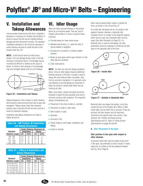
Idlers may be placed either inside or outside the<br />
drive, as shown in Fig. 26 and Fig. 27.<br />
An inside idler decreases the arc of contact on the<br />
adjacent sheaves; whereas, a backside idler<br />
increases the arc of contact on the adjacent sheaves.<br />
Either may be used, but a backside idler must be<br />
larger (See Idler Diameters on Page 81). If a<br />
backside idler is used for belt takeup, the idler<br />
penetration (amount of takeup) is limited by the belt<br />
span on the opposite side of the drive.<br />
Figure 26 – Inside Idler<br />
Figure 27 – Outside or Backside Idler<br />
Backside idlers are always flat pulleys, since they<br />
contact the top of the Polyflex JB or Micro-V <strong>Belt</strong>.<br />
Inside idlers can be either flat or grooved. If they are<br />
grooved, the idler sheave must be machined<br />
correctly for the specific belt cross section. (See<br />
Sections VIII. Polyflex JB Sheave Groove<br />
Specifications and IX., Micro-V Pulley Groove<br />
Specifications on pages 83 and 84.<br />
A. Idler Placement In the Span<br />
Idler position in the span with respect to<br />
other sheaves.<br />
A grooved inside idler may be located at any point<br />
in the span, but preferably so that it results in nearly<br />
equal arcs of contact on the two adjacent sheaves.<br />
See Fig. 28 on Page 81.<br />
80 The World’s Most Trusted Name in <strong>Belt</strong>s, Hose & Hydraulics.


