

PowerGrip® GT® Belt Drives
PowerGrip® GT® Belt Drives
PowerGrip® GT® Belt Drives

Create successful ePaper yourself
Turn your PDF publications into a flip-book with our unique Google optimized e-Paper software.
Polyflex ® JB ® and Micro-V ® <strong>Belt</strong>s – Engineering<br />
X. <strong>Belt</strong> Pull and Bearing Loads – continued<br />
B. For a two-sheave drive that requires only the<br />
magnitude of belt pull, use Formula 32 below:<br />
Formula 32<br />
<strong>Belt</strong> Pull = T T2 + T S2 + 2T T T S Cos (180 - ) , lb.<br />
Where: T T = Tightside tension, pounds<br />
TS = Slackside tension, pounds<br />
= Arc of contact on small sheave, degrees<br />
= 2 Cos -1 ( D - d ) 2CD<br />
Where: D = Large Diameter, inches<br />
d = Small Diameter, inches<br />
CD = Center Distance, inches<br />
<strong>Belt</strong> pull also may be determined by using the<br />
alternate procedure as follows:<br />
1. Add T T and T S (from Step 1 on Page 85 to find<br />
T T + T S (arithmetic sum.)<br />
2. Calculate D - d<br />
CD<br />
Where: D = Large Diameter, inches<br />
d = Small Diameter, inches<br />
CD = Center Distance, inches<br />
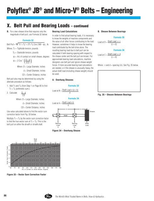
Use value calculated above to find the vector sum<br />
correction factor from Fig. 33 below.<br />
Multiply T T + T S by the vector sum correction factor<br />
to find the true vector sum of T T + T S . This is the<br />
belt pull on either the driveR or driveN shaft.<br />
Bearing Load Calculations<br />
In order to find actual bearing loads, it is necessary<br />
to know the weights of machine components and<br />
the value of all other forces contributing to the load.<br />
However, sometimes it helps to know the bearing<br />
load contributed by the belt drive alone. The<br />
resulting bearing load due to belt pull can be<br />
calculated if both bearing spacing with respect to<br />
the sheave center and the belt pull are known. For<br />
approximate bearing load calculations, machine<br />
designers use belt pull and ignore sheave weight<br />
forces. If more accurate bearing load calculations<br />
are needed, or if the sheave is unusually heavy, the<br />
actual shaft load (including sheave weight) should<br />
be used.<br />
A. Overhung Sheaves<br />
Formula 33<br />
Load at B = Shaft Load x (a + b)<br />
a<br />
Formula 34<br />
Load at A = Shaft Load x b<br />
a<br />
B. Sheave Between Bearings<br />
Formula 35<br />
Load at D = Shaft Load x c<br />
(c + d)<br />
Formula 36<br />
Load at C = Shaft Load x d<br />
(c + d)<br />
Where: c and d = spacing (in). See Fig. 35 below.<br />
Fig. 35 – Sheave Between Bearings<br />
Figure 34 – Overhung Sheave<br />
Figure 33 – Vector Sum Correction Factor<br />
86 The World’s Most Trusted Name in <strong>Belt</strong>s, Hose & Hydraulics.


