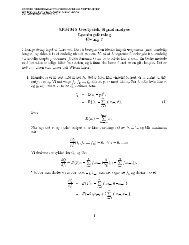
for the proposed 800 MW Combined Cycle Power Plant ...
for the proposed 800 MW Combined Cycle Power Plant ...
for the proposed 800 MW Combined Cycle Power Plant ...

Create successful ePaper yourself
Turn your PDF publications into a flip-book with our unique Google optimized e-Paper software.
CO 2 Capture Study<br />
For <strong>800</strong> <strong>MW</strong> <strong>Power</strong> <strong>Plant</strong> – Tjeldbergodden<br />
provide <strong>the</strong>rmal efficiency in <strong>the</strong> power cycle. Its consumption was based on a<br />
temperature rise of 10°C, which required a flow rate of 36750 tons per hour.<br />
It is <strong>proposed</strong> to install a booster pump to serve <strong>the</strong> carbon dioxide capture plant,<br />
which takes suction from <strong>the</strong> return sea water connection on <strong>the</strong> power plant<br />
condenser. It will boost <strong>the</strong> pressure so that <strong>the</strong>re is sufficient flow through <strong>the</strong><br />
carbon dioxide capture plant coolers and fill <strong>the</strong> system to its highest elevation,<br />
which is 6 meters above grade <strong>for</strong> <strong>the</strong> highest condenser.<br />
If <strong>the</strong>re is a weir box to control <strong>the</strong> pressure at <strong>the</strong> outlet of <strong>the</strong> power plant<br />
condenser, <strong>the</strong> suction to <strong>the</strong> booster pump and discharge from <strong>the</strong> carbon<br />
capture plant cooling system, may be made at this weir box without any<br />
connections to existing piping being required<br />
After passing through <strong>the</strong> heat exchangers <strong>the</strong> sea water is collected in <strong>the</strong> return<br />
main and is discharged to <strong>the</strong> outfall pit in <strong>the</strong> power plant. This prevents outlet<br />
sea water returning to <strong>the</strong> booster pump inlet.<br />
The system is depicted on <strong>the</strong> Cooling Water utility flow diagram, and <strong>the</strong> method<br />
of connection using <strong>the</strong> weir box in <strong>the</strong> outfall from <strong>the</strong> main power plant<br />
condenser is shown in <strong>the</strong> figure below<br />
Given a total flow of 41500 tons per hour <strong>the</strong> overall temperature rise is expected<br />
to be just above 14°C.<br />
To arrive at a specification <strong>for</strong> <strong>the</strong> booster pump an allowance of 0.7 Bar <strong>for</strong> <strong>the</strong><br />
pipework in addition to <strong>the</strong> 0.7 bar <strong>for</strong> <strong>the</strong> heat exchangers and 0.6 bar <strong>for</strong> <strong>the</strong><br />
control valves has been made. The static head difference between <strong>the</strong> level in<br />
<strong>the</strong> main weir box and <strong>the</strong> elevated weir box (see figure below) has been taken as<br />
7 metres. This give a total discharge pressure of 2.7 bar and <strong>for</strong> a flow of<br />
40000m3/h a hydraulic power of 3000kW is calculated. These are default values<br />
pending a full layout study and <strong>the</strong> investigation of operating some condensers<br />
under vacuum on <strong>the</strong> cooling water side. It is recognized <strong>the</strong>re<strong>for</strong>e that power<br />
consumptions could be optimized during plant design.<br />
CB2005-0022_Final Report.Doc