for the proposed 800 MW Combined Cycle Power Plant ...
for the proposed 800 MW Combined Cycle Power Plant ...
for the proposed 800 MW Combined Cycle Power Plant ...

You also want an ePaper? Increase the reach of your titles
YUMPU automatically turns print PDFs into web optimized ePapers that Google loves.
CO 2 Capture Study<br />
For <strong>800</strong> <strong>MW</strong> <strong>Power</strong> <strong>Plant</strong> – Tjeldbergodden<br />
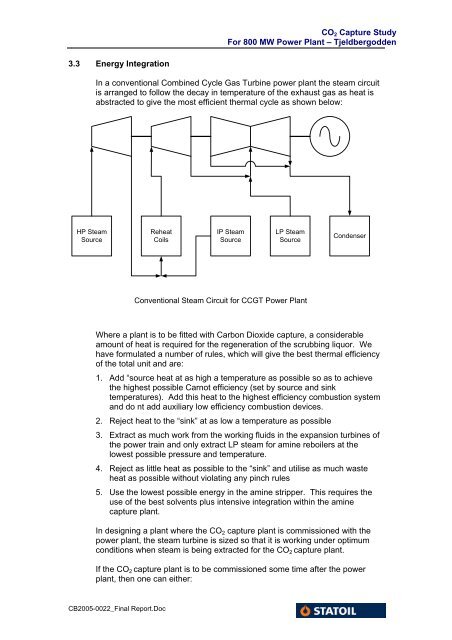
3.3 Energy Integration<br />
In a conventional <strong>Combined</strong> <strong>Cycle</strong> Gas Turbine power plant <strong>the</strong> steam circuit<br />
is arranged to follow <strong>the</strong> decay in temperature of <strong>the</strong> exhaust gas as heat is<br />
abstracted to give <strong>the</strong> most efficient <strong>the</strong>rmal cycle as shown below:<br />
HP Steam<br />
Source<br />
Reheat<br />
Coils<br />
IP Steam<br />
Source<br />
LP Steam<br />
Source<br />
Condenser<br />
Conventional Steam Circuit <strong>for</strong> CCGT <strong>Power</strong> <strong>Plant</strong><br />
Where a plant is to be fitted with Carbon Dioxide capture, a considerable<br />
amount of heat is required <strong>for</strong> <strong>the</strong> regeneration of <strong>the</strong> scrubbing liquor. We<br />
have <strong>for</strong>mulated a number of rules, which will give <strong>the</strong> best <strong>the</strong>rmal efficiency<br />
of <strong>the</strong> total unit and are:<br />
1. Add “source heat at as high a temperature as possible so as to achieve<br />
<strong>the</strong> highest possible Carnot efficiency (set by source and sink<br />
temperatures). Add this heat to <strong>the</strong> highest efficiency combustion system<br />
and do nt add auxiliary low efficiency combustion devices.<br />
2. Reject heat to <strong>the</strong> “sink” at as low a temperature as possible<br />
3. Extract as much work from <strong>the</strong> working fluids in <strong>the</strong> expansion turbines of<br />
<strong>the</strong> power train and only extract LP steam <strong>for</strong> amine reboilers at <strong>the</strong><br />
lowest possible pressure and temperature.<br />
4. Reject as little heat as possible to <strong>the</strong> “sink” and utilise as much waste<br />
heat as possible without violating any pinch rules<br />
5. Use <strong>the</strong> lowest possible energy in <strong>the</strong> amine stripper. This requires <strong>the</strong><br />
use of <strong>the</strong> best solvents plus intensive integration within <strong>the</strong> amine<br />
capture plant.<br />
In designing a plant where <strong>the</strong> CO 2 capture plant is commissioned with <strong>the</strong><br />
power plant, <strong>the</strong> steam turbine is sized so that it is working under optimum<br />
conditions when steam is being extracted <strong>for</strong> <strong>the</strong> CO 2 capture plant.<br />
If <strong>the</strong> CO 2 capture plant is to be commissioned some time after <strong>the</strong> power<br />
plant, <strong>the</strong>n one can ei<strong>the</strong>r:<br />
CB2005-0022_Final Report.Doc