

Application Note AN-1035 - International Rectifier
Application Note AN-1035 - International Rectifier
Application Note AN-1035 - International Rectifier

You also want an ePaper? Increase the reach of your titles
YUMPU automatically turns print PDFs into web optimized ePapers that Google loves.
7. Heat the site to approximately 100°C (150°C for<br />
lead-free assembly) using the substrate heating<br />
stage.<br />
8. Use the de-soldering tool to heat both device and<br />
solder interconnects to reflow temperature,<br />
waiting until all the solder has reflowed.<br />
9. Retract the arm, leaving the device in place. Cool<br />
as quickly as possible.<br />
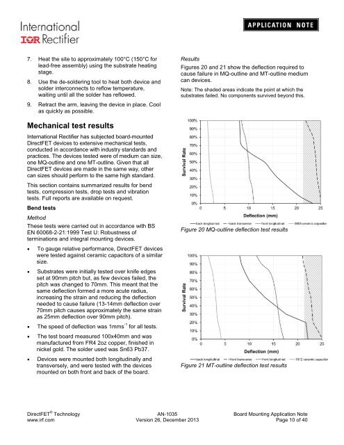
Results<br />
Figures 20 and 21 show the deflection required to<br />
cause failure in MQ-outline and MT-outline medium<br />
can devices.<br />
<strong>Note</strong>: The shaded areas indicate the point at which the<br />
substrates failed. No components survived beyond this.<br />
Mechanical test results<br />
<strong>International</strong> <strong>Rectifier</strong> has subjected board-mounted<br />
DirectFET devices to extensive mechanical tests,<br />
conducted in accordance with industry standards and<br />
practices. The devices tested were of medium can size,<br />
one MQ-outline and one MT-outline. Given that all<br />
DirectFET devices are made in the same way, other<br />
can sizes should perform to the same high standard.<br />
This section contains summarized results for bend<br />
tests, compression tests, drop tests and vibration<br />
tests. Full reports are available on request.<br />
Bend tests<br />
Method<br />
These tests were carried out in accordance with BS<br />
EN 60068-2-21:1999 Test U: Robustness of<br />
terminations and integral mounting devices.<br />
Figure 20 MQ-outline deflection test results<br />
• To gauge relative performance, DirectFET devices<br />
were tested against ceramic capacitors of a similar<br />
size.<br />
• Substrates were initially tested over knife edges<br />
set at 90mm pitch but, as few devices failed, the<br />
pitch was changed to 70mm. This meant that the<br />
same deflection formed a more acute radius,<br />
increasing the strain and reducing the deflection<br />
needed to cause failure (13-14mm deflection over<br />
70mm pitch causes approximately the same strain<br />
as 25mm deflection over 90mm pitch).<br />
• The speed of deflection was 1mms -1 for all tests.<br />
• The test board measured 100x40mm and was<br />
manufactured from FR4 2oz copper, finished in<br />
nickel gold. The solder used was Sn63 Pb37.<br />
• Devices were mounted both longitudinally and<br />
transversely, and were tested with the devices<br />
mounted on both front and back of the board.<br />
Figure 21 MT-outline deflection test results<br />
DirectFET ® Technology <strong>AN</strong>-<strong>1035</strong> Board Mounting <strong>Application</strong> <strong>Note</strong><br />
www.irf.com Version 26, December 2013 Page 10 of 40


