

Application Note AN-1035 - International Rectifier
Application Note AN-1035 - International Rectifier
Application Note AN-1035 - International Rectifier

Create successful ePaper yourself
Turn your PDF publications into a flip-book with our unique Google optimized e-Paper software.
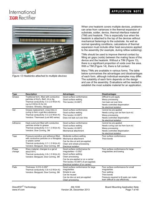
Figure 12 Heatsinks attached to multiple devices<br />
When one heatsink covers multiple devices, problems<br />
can arise from variances in the thermal expansion of<br />
substrate, solder, device, thermal interface material<br />
(TIM) and heatsink. This is especially true when the<br />
heatsink is attached to the top of the devices without<br />
mechanical fastenings to the substrate. As well as<br />
normal operating conditions, calculations of thermal<br />
expansion must include other heat excursions applied<br />
to the assembly (for example, during reflow soldering).<br />
TIMs should be used to improve thermal contact by<br />
filling air gaps (voids) between the mating faces of the<br />
device and the heatsink. Without a TIM (Figure 13),<br />
there is a significant proportion of voids over the area.<br />
With a TIM (Figure 14), there is full contact.<br />
Many TIMs are available in various forms. The table<br />
below summarises the advantages and disadvantages<br />
of each form, although individual examples may differ.<br />
The suitability of each form depends on the design<br />
and use of the assembly. Evaluations will be needed to<br />
establish the most suitable material for an application.<br />
Type Description Advantages Disadvantages<br />
Grease Traditional form, filled with conductive<br />
particles of Al 2O 3, BeO, Al or Ag<br />
Thermal conductivity: 0.3–2.0 W/(m·K)<br />
(up to 6 W/(m·K) for Al)<br />
Vendors: Shinetsu, Bergquist<br />
Good surface conformance<br />
Good surface wetting<br />
Thin bonds (


