FPGA based Hardware Accleration for Elliptic Curve Cryptography ...
FPGA based Hardware Accleration for Elliptic Curve Cryptography ...
FPGA based Hardware Accleration for Elliptic Curve Cryptography ...

Create successful ePaper yourself
Turn your PDF publications into a flip-book with our unique Google optimized e-Paper software.
Fachbereich In<strong>for</strong>matik<br />
Integrierte Schaltungen und Systeme<br />
Prof. Dr.-Ing. Sorin Huss<br />
Studienarbeit<br />
<strong>FPGA</strong> <strong>based</strong> <strong>Hardware</strong> Acceleration <strong>for</strong><br />
<strong>Elliptic</strong> <strong>Curve</strong> <strong>Cryptography</strong> <strong>based</strong> on ¢¡¤£¦¥¨§©<br />
Felix Madlener<br />
madlener@iss.tu-darmstadt.de<br />
Matr.-Nr.: 948463<br />
Betreuer : Dipl.-In<strong>for</strong>m. Markus Ernst<br />
Ausgabe : 01.02.2002<br />
Abgabe : 30.08.2002
Zusicherung<br />
Zur Erstellung der vorliegenden Studienarbeit wurden nur die in der Arbeit angegebenen Hilfsmittel verwendet.<br />
Felix Madlener
Contents<br />
List of Figures<br />
iv<br />
1 Introduction 1<br />
1.1 Motivation . . . . . . . . . . . . . . . . . . . . . . . . . . . . . . . . . . . . . . . . . . . . 1<br />
1.2 Previous Work . . . . . . . . . . . . . . . . . . . . . . . . . . . . . . . . . . . . . . . . . . 2<br />
1.3 Goals of this Study . . . . . . . . . . . . . . . . . . . . . . . . . . . . . . . . . . . . . . . 3<br />
1.4 Content of this work . . . . . . . . . . . . . . . . . . . . . . . . . . . . . . . . . . . . . . 3<br />
(<br />
Field<br />
over<br />
Fields<br />
in<br />
in<br />
in<br />
in<br />
2 Mathematical Background 4<br />
2.1 <strong>Elliptic</strong> <strong>Curve</strong> Arithmetic . . . . . . . . . . . . . . . . . . . . . . . . . . . . . . . . . . . . 4<br />
2.1.1 Affine Coordinates . . . . . . . . . . . . . . . . . . . . . . . . . . . . . . . . . . . 4<br />
2.1.2 Projective Coordinates . . . . . . . . . . . . . . . . . . . . . . . . . . . . . . . . . 6<br />
2.1.3 EC point multiplication ) . . . . . . . . . . . . . . . . . . . . . . . . . . . . . 7<br />
2.2 Finite Field Arithmetic . . . . . . . . . . . . . . . . . . . . . . . . . . . . . . . . . . . . . 8<br />
2.2.1 The Finite . . . . . . . . . . . . . . . . . . . . . . . . . . . . . . . . . 9<br />
2.2.2 Polynomial Rings . . . . . . . . . . . . . . . . . . . . . . . . . . . . . 9<br />
2.2.3 Finite . . . . . . . . . . . . . . . . . . . . . . . . . . . . . . . . . . 9<br />
2.2.4 Addition . . . . . . . . . . . . . . . . . . . . . . . . . . . . . . . . . . 10<br />
2.2.5 Multiplication . . . . . . . . . . . . . . . . . . . . . . . . . . . . . . . 10<br />
2.2.6 Squaring . . . . . . . . . . . . . . . . . . . . . . . . . . . . . . . . . . 10<br />
2.2.7 Inversion . . . . . . . . . . . . . . . . . . . . . . . . . . . . . . . . . . 10<br />
2.2.8 Polynomial Reduction . . . . . . . . . . . . . . . . . . . . . . . . . . . . . . . . . 11<br />
2.3 Sequential Multiplication Schemes . . . . . . . . . . . . . . . . . . . . . . . . . . . . . . . 13<br />
2.3.1 Schoolbook Multiplication . . . . . . . . . . . . . . . . . . . . . . . . . . . . . . . 13<br />
2.3.2 Polynomial Karatsuba Multiplication . . . . . . . . . . . . . . . . . . . . . . . . . 15<br />
2.3.3 Multi-Segment Karatsuba Multiplication . . . . . . . . . . . . . . . . . . . . . . . 16<br />
3 <strong>Hardware</strong> Architecture 19<br />
3.1 PCI Interface . . . . . . . . . . . . . . . . . . . . . . . . . . . . . . . . . . . . . . . . . . 19<br />
3.2 Register File . . . . . . . . . . . . . . . . . . . . . . . . . . . . . . . . . . . . . . . . . . . 20<br />
3.3 EC Arithmetic . . . . . . . . . . . . . . . . . . . . . . . . . . . . . . . . . . . . . . . . . . 20<br />
3.4 Finite Field Arithmetic . . . . . . . . . . . . . . . . . . . . . . . . . . . . . . . . . . . . . 20<br />
3.4.1 Addition . . . . . . . . . . . . . . . . . . . . . . . . . . . . . . . . . . . . . . . . 20<br />
3.4.2 Square . . . . . . . . . . . . . . . . . . . . . . . . . . . . . . . . . . . . . . . . . 21<br />
3.4.3 Input Stage . . . . . . . . . . . . . . . . . . . . . . . . . . . . . . . . . . . . . . . 22
CONTENTS<br />
iii<br />
3.4.4 Combinational Multiplier (CKM) . . . . . . . . . . . . . . . . . . . . . . . . . . . 22<br />
3.4.5 MSK Pattern Generation . . . . . . . . . . . . . . . . . . . . . . . . . . . . . . . . 23<br />
3.4.6 Interleaved Polynomial Reduction . . . . . . . . . . . . . . . . . . . . . . . . . . . 24<br />
3.5 VHDL-Code Generator . . . . . . . . . . . . . . . . . . . . . . . . . . . . . . . . . . . . . 25<br />
3.6 Evaluation Software . . . . . . . . . . . . . . . . . . . . . . . . . . . . . . . . . . . . . . . 26<br />
4 Implementation Results 27<br />
4.1 Xilinx XC4085XLA . . . . . . . . . . . . . . . . . . . . . . . . . . . . . . . . . . . . . . 27<br />
4.2 Xilinx XCV405E . . . . . . . . . . . . . . . . . . . . . . . . . . . . . . . . . . . . . . . . 28<br />
4.3 Atmel AT94K40 . . . . . . . . . . . . . . . . . . . . . . . . . . . . . . . . . . . . . . . . . 28<br />
4.4 Comparison . . . . . . . . . . . . . . . . . . . . . . . . . . . . . . . . . . . . . . . . . . . 29<br />
5 Conclusions and Outlook 30<br />
5.1 Summary . . . . . . . . . . . . . . . . . . . . . . . . . . . . . . . . . . . . . . . . . . . . 30<br />
5.2 Further Work . . . . . . . . . . . . . . . . . . . . . . . . . . . . . . . . . . . . . . . . . . 30<br />
Bibliography 31<br />
Annex 34<br />
3-Segment Karatsuba Multiplication . . . . . . . . . . . . . . . . . . . . . . . . . . . . . . . . . 34<br />
2P Algorithm . . . . . . . . . . . . . . . . . . . . . . . . . . . . . . . . . . . . . . . . . . . . . 35
List of Figures<br />
c)! #"%$ d)& #"'$<br />
2.1 Example of an EC visualizing the point addition . . . . . . . . . . . . . . . . . . . . . . . . 5<br />
2.2 EC arithmetic hierarchy . . . . . . . . . . . . . . . . . . . . . . . . . . . . . . . . . . . . . 8<br />
2.3 Structure of the polynomial reduction . . . . . . . . . . . . . . . . . . . . . . . . . . . . . 12<br />
2.4 Sequential Multiplication Schemes: a) Schoolbook method; b) unrolled Karatsuba <strong>for</strong> 2<br />
recursion steps; be<strong>for</strong>e reordering of the subterms; after reordering of<br />
the subterms . . . . . . . . . . . . . . . . . . . . . . . . . . . . . . . . . . . . . . . . . . . 14<br />
2.5 Polynomial Karatsuba multiplication scheme . . . . . . . . . . . . . . . . . . . . . . . . . 16<br />
of(*),+<br />
3.1 Generic Datapath of the EC coprocessor . . . . . . . . . . . . . . . . . . . . . . . . . . . . 19<br />
3.2 Generic Datapath of the Finite Field Arithmetic . . . . . . . . . . . . . . . . . . . . . . . . 21<br />
3.3 Recursive construction process <strong>for</strong> polynomial Karatsuba multipliers . . . . . . . . . . . . . 22<br />
3.4 Combinational Karatsuba Multiplier gate count . . . . . . . . . . . . . . . . . . . . . . . . 23<br />
3.5 Structure of the polynomial reduction bit . . . . . . . . . . . . . . . . . . . . . . 24<br />
4.1 microEnable PCI card . . . . . . . . . . . . . . . . . . . . . . . . . . . . . . . . . . . . . . 27<br />
4.2 Atmel AT94K40 . . . . . . . . . . . . . . . . . . . . . . . . . . . . . . . . . . . . . . . . . 28
Chapter 1<br />
Introduction<br />
1.1 Motivation<br />
Today there is a wide range of distributed systems, which use communication resources that can not be<br />
safeguarded against eavesdropping or unauthorized data alteration. Thus cryptographic protocols are applied<br />
to these systems in order to prevent in<strong>for</strong>mation extraction or to detect data manipulation by unauthorized<br />
parties.<br />
In general, cryptographic methods can be subdivided into two categories: symmetric- and asymmetric<br />
cryptographic algorithms.<br />
In the case of symmetric cryptographic algorithms like DES [1] or AES [2] both communication partners<br />
use the same secret key to encrypt and decrypt messages. Compared to asymmetric cryptography these<br />
algorithms are considered to be faster and more efficient. However, the general problem of symmetric<br />
methods is the distribution of the secret key. Sender and recipient both have to possess the same secret key<br />
to process the message but no one else may have the key, because otherwise one would be able to decrypt<br />
or alter the message just like the original author and recipient. So secure channels have to be established in<br />
order to exchange the keys.<br />
With regard of this problem, asymmetric algorithms have been developed. These algorithms, which are<br />
also called public key algorithms, differ in the utilized set of keys consisting of a public- and a private key.<br />
This key pair can only be computed by the original creator of the keys. For all others both keys are virtually<br />
independent. The general principle of all public key schemes is then, that a message that is encrypted with<br />
one of the keys can only be decrypted with the other one.<br />
After publication of the public key, everyone can use this key, e.g. to encrypt a message. Afterwards,<br />
this message can only be decrypted with the corresponding private key which is exclusively known by the<br />
authorized recipient of the message.<br />
Alternatively, public key algorithms can be used to compute and verify digital signatures. The author of<br />
a message uses his secret, private key to compute a signature. By looking up the authors public key any<br />
recipient of the message-signature-pair is able to verify this signature subsequently.<br />
Public key algorithms provide much flexibility and a very high level of security. On the other hand,<br />
in comparison to symmetric methods, they are <strong>based</strong> on much more complex and expensive arithmetic<br />
operations. In practice a combination of both methods is frequently used. E.g. SSL [3]: public key methods<br />
are used <strong>for</strong> key exchange and authentication while symmetric algorithms are applied <strong>for</strong> the encryption of<br />
the data stream.<br />
The most prominent public key method is the widely-used RSA algorithm [4]. It is <strong>based</strong> on the problem
1.2. PREVIOUS WORK 2<br />
of dividing a large number into it’s prime factors, a problem that is considered to be hard, meaning it can<br />
not be calculated in polynomial time.<br />
Un<strong>for</strong>tunately it is not known if this problem is really hard (though it’s quite probable). If someone would<br />
develop an algorithm to calculate the prime factors efficiently, the RSA scheme would become insecure<br />
immediately. This problematic leaded to the need of alternatives in public key cryptography. The main<br />
requirement <strong>for</strong> such alternatives is the use of different underlying mathematical problems, which should<br />
optimally be as well researched as the problem of dividing large numbers into prime factors.<br />
One of the most important alternative public-key schemes is <strong>based</strong> on the discrete logarithm problem<br />
(DLP) on elliptic curves (EC). In 1985 elliptic curve cryptography (ECC) has been first proposed by<br />
V. Miller [5] and N. Koblitz [6] independently. In the following a lot of research has been done and nowadays<br />
ECC is widely known and accepted. Because EC methods in general are believed to give a higher<br />
security per key bit in comparison to RSA (1024 RSA-bits are equivalent to 160 EC-bits), one can work<br />
with shorter keys in order to achieve the same level of security [7]. The smaller key size permits more<br />
cost-efficient implementations, which is of special interest <strong>for</strong> hardware implementations and systems with<br />
low computing power.<br />
ECC is <strong>based</strong> on a set of points on elliptic curves and their arithmetic operations EC-Add and EC-Double.<br />
These EC operations are in turn composed of arithmetic operations in the underlying finite field (FF). Here,<br />
the most expensive and complex operation is the field multiplication FF-Mult. The finite -. field ,<br />
which is characteristic of and degree( extension is treated throughout this work.<br />
Each application has different demands on the utilized cryptosystem (e.g., in terms of required bandwidth,<br />
level of security, incurred cost per node and number of communicating partners). Corresponding to the<br />
growing number of ECC clients, there is also a need <strong>for</strong> high per<strong>for</strong>mance server implementations. Such an<br />
implementation should be capable of processing different cryptographic parameter sets (in special different<br />
bit widths) at high speed.<br />
Depending on the application, the per<strong>for</strong>mance of genuine SW implementations of EC cryptosystems may<br />
not be sufficient. In this work a generic and scalable architecture of an ECC coprocessor has been developed.<br />
The presented prototype implementations are <strong>based</strong> on different reconfigurable Field Programmable Gate<br />
Array (<strong>FPGA</strong>) devices from Xilinx [8] and Atmel [9].<br />
The main focus of this work is the acceleration of the field multiplication FF-Mult. This is realized<br />
by combining a fast and resource efficient combinational multiplier with a novel scheme <strong>for</strong> sequential<br />
multiplication called multi-segment Karatsuba multiplication (MSK). A clever structuring of the datapath<br />
together with well fitting EC level algorithms leads to highly efficient implementations of EC cryptosystems.<br />
1.2 Previous Work<br />
Concerning EC coprocessor designs, there is some previous work at the institute, on which this work is<br />
relying on. In contrast to the polynomial base representation treated here, this previous hardware implementation<br />
(documented in [10]) is <strong>based</strong> on an Optimal Normal Basis (ONB) representation of the field<br />
elements.<br />
The manner how basic arithmetic operations in have to be per<strong>for</strong>med depends on the utilized<br />
field representation. Especially the multiplication in is completely different when comparing ONB<br />
against polynomial base arithmetic. However, the top-level EC algorithms do not depend on field representation<br />
and could there<strong>for</strong>e be partially reused within this work.<br />
The microEnable <strong>FPGA</strong> card, which is one of the utilized hardware plat<strong>for</strong>ms in Chap. 4, has been already<br />
used <strong>for</strong> the implementation of the ONB <strong>based</strong> design. The idea of using a generator approach to derive
1.3. GOALS OF THIS STUDY 3<br />
specific and synthesizable VHDL descriptions from a superior, generic coprocessor-model has also been<br />
adopted from this previous design.<br />
1.3 Goals of this Study<br />
The main goal of this work is the design and the implementation of a arithmetic processor kernel<br />
which can be embedded into the previously described EC coprocessor design. After some research on<br />
existing algorithms and implementations it was decided that the main work should concentrate on the finite<br />
field arithmetic while the EC level algorithms should be adopted from the literature. The main reason <strong>for</strong> this<br />
decision was the fact, that an efficient hardware architecture has a much greater influence on the efficiency<br />
of the data flow dominated finite field algorithms than on the control flow oriented EC level algorithms.<br />
The final design should be widely scalable in terms of different types of resource usage. To provide this<br />
scalability and flexibility a generator program should be used to produce the VHDL hardware models, out<br />
of which the <strong>FPGA</strong> programming bitstream is synthesized subsequently. While it was clear that the most<br />
important parameter <strong>for</strong> scalability will be the bitwidth of the design, the complete parameter set and the<br />
resulting degree of flexibility caused by the generator approach was specified during the implementation<br />
progress.<br />
A minor goal has been the compatibility to existing modules. The interface of the new developed design<br />
should correspond to that of the existing ONB implementation. Using this goal it was possible to reuse the<br />
already optimized EC Controller from the ONB implementation without modifications.<br />
A new family of attacks against cryptographic hardware implementations is currently gaining much importance.<br />
These so called Side-Channel-Attacks use additional in<strong>for</strong>mation the hardware provides beside the<br />
cryptographic functions to extract knowledge of the secret key. Examples <strong>for</strong> this additional in<strong>for</strong>mation are<br />
the runtime of an operation that might depend on the secret key or the power consumption of a chip during<br />
the computation. Though it was not a main goal of this work to provide resistance against such attacks, the<br />
problem should be reminded during implementation. Where possible, simple countermeasures should be<br />
implemented.<br />
To evaluate the functionality of the hardware implementation, the results should be compared against<br />
results of a pure software implementation. To provide a framework <strong>for</strong> this evaluation process, the existing<br />
C software implementation has been extended to support- elements in polynomial representation.<br />
1.4 Content of this work<br />
The mathematical background of elliptic curves and finite fields is introduced in the following chapter.<br />
Furthermore, the multi-segment Karatsuba multiplication scheme is described in detail. Chap. 3 focuses on<br />
the architecture and the implementation of the proposed ECC coprocessor. Special attention is given to the<br />
arithmetic processor kernel. Implementation results and some per<strong>for</strong>mance numbers are given in<br />
Chap. 4. Finally, Chap. 5 summarizes the conclusions and gives an outlook on work that might follow.
Chapter 2<br />
Mathematical Background<br />
There are several cryptographic schemes <strong>based</strong> on elliptic curves. These schemes work on a subgroup of<br />
points of an EC over a finite field. Arbitrary finite fields are approved to be suitable <strong>for</strong> ECC. This work<br />
concentrates on elliptic curves over the finite field- and their arithmetics only. For further in<strong>for</strong>mation<br />
see [11] and [12].<br />
There are several bases known <strong>for</strong> . The most common bases, which are also proposed by the<br />
leading standards concerning ECC (IEEE 1363 [13] and ANSI X9.62 [14]) are polynomial bases and normal<br />
bases. Please remark, that the design detailed in the following is exclusively treating with polynomial basis<br />
representation.<br />
Sec. 2.1 introduces some basic facts and algorithms of elliptic curves. In Sec. 2.2 a short review on the finite<br />
field <strong>based</strong> on polynomial basis representation is given. Sec. 2.3 presents several multiplication<br />
schemes in- and leads to the multi-segment Karatsuba multiplication algorithm which is one main<br />
contribution of this work.<br />
2.1 <strong>Elliptic</strong> <strong>Curve</strong> Arithmetic<br />
2.1.1 Affine Coordinates<br />
An elliptic curve over is defined as the cubic equation<br />
),5 176 598:) (2.1)<br />
/¢02143<br />
1FE and>HG 6!I<br />
. The set of solutions J=K5D@ 1 ML 1 3 )?5 1N6 5 8 )O;P5 3 )Q>SR is called the<br />
points of the elliptic curve/<br />
. By defining an appropriate addition operation and an extra pointT , called the<br />
with;9@A>B@C5D@<br />
point at infinity, these points become an additive, abelian withT group the neutral element.<br />
Fig. 2.1 depicts an example of an elliptic curve over the reals. Here, a geometric interpretation of the<br />
addition can be given: Find the third intersection (-U point ) of a straight line through V and with the<br />
elliptic curve. resultU<br />
6 Q)WV The is found by -U mirroring at the x-axis.
V (EC-Add), ^ 6 1 3_ 1 Y 6<br />
then<br />
3 ^ ^<br />
) 6<br />
8<br />
1<br />
6 V 6 K5D@ 1 (EC-Double), then ^ 6 57)<br />
If<br />
1<br />
8<br />
1<br />
5<br />
^<br />
2.1. ELLIPTIC CURVE ARITHMETIC 5<br />
Figure 2.1: Example of an EC visualizing the point addition<br />
For an curve/<br />
elliptic over- defined the basic operation of points¨@XV<br />
EQ/<br />
adding with<br />
6<br />
K5DYZ@ 1 Y[ andV<br />
6 K5 3 @ 1 3 <br />
,<br />
is as follows:<br />
U 6 Q)WV 6 K5 8 @ 1<br />
8 9\<br />
If]G<br />
5 3_ 5`Y<br />
),5`Ya)
Ymonpn _ #qkr9;=stPuiY[ v<br />
l<br />
_ wr9xKyhzf 3 @ l Y[ v monMn _ v-{P{ v @gfDYh<br />
monMn<br />
monMn _ wr9xKyhKe 3 @XijY[ |<br />
monMn _ v-{P{ | @Ce'Yh }<br />
|<br />
_ 2rx~yui Y @ | € m nMn _ wr9xKyhl Y @g;<br />
monpn<br />
m nMn _ v-{P{ € @ } €<br />
Y monpn _ #qkr9;=stP| €<br />
l<br />
nMn _ wr9xKyhl Y @ € m<br />
monpn _ 2rxKyhv @ } /<br />
l Ymonpn _ #qkr9;=stPv <br />
monpn _ 2rx~yzf 3 @Xi 8 „<br />
„<br />
_ vƒ{={ „ @Ce 8 monpn<br />
Ymonpn _ 2rxKyhui 8 @ „ l<br />
2.1. ELLIPTIC CURVE ARITHMETIC 6<br />
Algorithm 1 EC-Add<br />
Input:<br />
6 KeNYS@gfDYh@XijY[X@XV 6 Ke 3 @gf 3 @ZcS 1E :k<br />
Output:U<br />
6 Q)WV 6 Ke 8 @gf 8 @Xi 8 E -k.<br />
i 8 monpn _ #qkr9;=st=} <br />
e 8 m‚npn _ v-{P{ € @ / <br />
e 8 m‚npn _ v-{P{ Ke 8 @ l Y[<br />
n!monpn _ 2rx~yKe 3 @Xi 8 <br />
n!monpn _ vƒ{={ zn@Ce 8 <br />
f 8 monpn _ 2rxKyh/ @gn…<br />
f 8 monpn _ vƒ{={ zf 8 @ l Y[<br />
returnKe<br />
8 @gf 8 @Xi 8 <br />
2.1.2 Projective Coordinates<br />
Computing inverses in is relatively expensive in comparison to multiplication. One may switch to<br />
projective coordinates in order to avoid computing inverses. The hardware implementation presented in this<br />
work is <strong>based</strong> on the projective representation detailed in [15].<br />
Replacing5<br />
6 e%†i and176 f†i 3<br />
in Eqn. 2.1 leads to the EC equation<br />
3 )‡ê f‰i 6 e 8 i‡)i $ \ (2.2)<br />
f<br />
An point<br />
6 K5b@ 1 affine is converted into its projective representation settinge<br />
6 5 ,f 6Š1<br />
by<br />
i 6 c<br />
and<br />
. The conversion from projective to affine is done as stated be<strong>for</strong>e by 5 6 e%†i computing<br />
1*6 f†i 3<br />
and<br />
.<br />
Applying these projective coordinates an EC-Add operation can be per<strong>for</strong>med with Alg. 1 and the corresponding<br />
EC-Double algorithm is given by Alg. 2. Thus, computing (,)‹V EC-Add ) requires 10 multipli-<br />
1 We can fixŒ9`Ž because the base point‘’bŽ”“–•’A—˜h’g will always be added during the computation of the point multiplicationš›‘<br />
.
Ymonpn _ #qkr9;=stPKe'Y[ l<br />
l<br />
monpn _ #qkr9;=stPuiY[ 3<br />
3 monpn _ #qkr9;=stPl 3 l<br />
l<br />
monpn _ 2rxKyhl 3 @A> Y<br />
3 monpn _ #qkr9;=stPzf Y l<br />
l<br />
monpn _ vƒ{={ l 3 @ l Y l Ymonpn _ 2rxKyhz;9@Xi<br />
3<br />
l Ymonpn _ vƒ{={ l YS@ l 3 8<br />
l Ymonpn _ 2rxKyhl YZ@Ce 8 <br />
2.1. ELLIPTIC CURVE ARITHMETIC 7<br />
Algorithm 2 EC-Double<br />
Input:<br />
6 KeNYS@gfDYh@XijY[ E -k<br />
Output:Q)<<br />
6 ¦ E ¦.<br />
8 monpn _ 2rx~yl YZ@ l 3 <br />
e<br />
i<br />
m‚npn _ œqBr;Pst=l YX 8<br />
e 8 m‚npn _ v-{P{ Ke 8 @ l Y <br />
f 8 monpn _ 2rxKyhl Y @Xi 8 <br />
8 monpn _ vƒ{={ zf 8 @ l Y[<br />
returnKe<br />
f<br />
@gf 8 @Xi 8 8<br />
cations, 8 additions and 4 square operations. The computation of (4 EC-Double ) requires multiplications,<br />
4 additions and 5 squares. All these operations have to be done in the underlying finite field.<br />
2.1.3 EC point multiplication (žbŸ¡ )<br />
Since the points on an elliptic curve/<br />
<strong>for</strong>m an additive group, there is no inner group operation like the<br />
multiplication. Even so repeated point additions such as<br />
§Z 6 U 6<br />
Ë /<br />
and<br />
E'©ª<br />
, are usually considered as the operation called EC point multiplication.<br />
Based on this operation, a discrete logarithm problem <strong>for</strong> elliptic curves can be <strong>for</strong>mulated. A problem,<br />
that is considered to be a secure cryptographic function. A secure cryptographic function in this terms<br />
with@gU<br />
means, the ofU calculation of and out can be per<strong>for</strong>med quite efficient while it is hardly possible<br />
compute<br />
to<br />
only andU if known. are is called the discrete ofU logarithm to base the .<br />
The level of security, ECC provides directly follows from the bitwidth the numbers in the underlying<br />
finite field. Currently bitwidths ranging from 113 bit (<strong>for</strong> low security applications) up to about 409 bit (<strong>for</strong><br />
very high security applications) are utilized.<br />
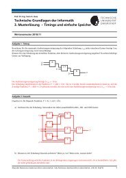
The hierarchy of arithmetics <strong>for</strong> an EC point multiplication is depicted in Fig. 2.2. The level top algorithm<br />
is per<strong>for</strong>med by repeated EC-Add and EC-Double operations. The EC operations in turn are composed<br />
of basic operations in the underlying field. The proposed finite field arithmetic is capable to compute the<br />
FF-Add and FF-Square operations within one clock cycle. The operation FF-Mult is more costly. The<br />
number of clock cycles <strong>for</strong> its computation depends on the number of segments used in the FF multiplier<br />
(see Sec. 2.3.3 <strong>for</strong> details).<br />
¦<br />
times<br />
¢ £h¤ ¥ d),d)o\\\)
2.2. FINITE FIELD ARITHMETIC 8<br />
k P<br />
EC-Double<br />
EC-Add<br />
FF-Mult<br />
FF-Add<br />
FF-Square<br />
Figure 2.2: EC arithmetic hierarchy<br />
By exploiting the previously detailed projective coordinates during the computation of a operation all<br />
but one field inversion can be circumvented. This inversion, that takes place at the end of a operation,<br />
converts the result that is given in projective coordinates back to the affine representation. Compared to the<br />
number of cycles a complete operation takes, the time <strong>for</strong> this single inversion is negligible. There<strong>for</strong>e<br />
it can be computed using a simple algorithm <strong>based</strong> on the existing field operations FF-Square, FF-Mult and<br />
FF-Add (see Sec. 2.2.6).<br />
Depending on different constraints one can chose from a lot of different algorithms on all level of arithmetic.<br />
For the operations, this work applies the Double-And-Add algorithm given in Alg. 3. The algorithm<br />
simply scans bit-by-bit. If the current bit is set ( 6 c ), the intermediate result is doubled and the base<br />
point is added one time. If the bit is not set ( 6«I<br />
), only the EC-Double operation is per<strong>for</strong>med.<br />
Using precomputated values would allow to scan multiple bits at one time and by that would lead to an<br />
improved per<strong>for</strong>mance. Due to space limitations the additional registers that would be needed to store these<br />
precomputated values were the main reason not to implement such an algorithm.<br />
Using Alg. 3 each multiplication requires( EC-Double and¬ EC-Add operations. As EC-Double is<br />
cheaper in terms of FF multiplication as EC-Add, the per<strong>for</strong>mance of the algorithm benefits from a key<br />
with low Hamming weight¬ .<br />
2.2 Finite Field Arithmetic<br />
The finite field- is the underlying field on which elliptic curves are <strong>based</strong> throughout this work. It<br />
can be viewed as a vector space of dimension( over the field . In hardware field elements can be<br />
easily implemented as a bit vector, which makes this kind of finite fields especially interesting <strong>for</strong> hardware<br />
implementations. As already mentioned, the representation treated in this paper is a polynomial basis only.
2.2.2 Polynomial Rings over·7¸À¹4»<br />
2.2. FINITE FIELD ARITHMETIC 9<br />
Algorithm 3 Double-And-Add<br />
Input:<br />
6 = Y@\\\S@AYZ@AP®S3 and<br />
Ë /<br />
m ¯ _ c ¯<br />
end while<br />
I<br />
then<br />
Vwm <br />
if¯:´<br />
m ¯ _ c ¯<br />
6 ¯ m°( _ c<br />
Output:V<br />
6²I and¯³ I<br />
do<br />
while±<br />
while¯³ I<br />
do<br />
/ } _ €Hµ r>[xtPuV…<br />
if ± 6 c then<br />
Vwm<br />
/ } _ v-{P{ uV§@g…<br />
end if<br />
Vwm<br />
m ¯ _ c ¯<br />
end while<br />
else<br />
end if<br />
VwmoT<br />
2.2.1 The Field·§¸º¹»<br />
Finite<br />
The smallest imaginable finite is- 6½¼ †¦ field , which has two elements only: The additive and the<br />
multiplicative elementsI<br />
andc neutral respectively. Its addition and multiplication tables resemble the truth<br />
tables of the binary (¾ XOR ) and the binary (¿ AND ) operation respectively. The elements can directly<br />
represented by a single bit.<br />
returnV<br />
sethÁ5à6 J¦ÄÆÅ ±ÈÇÉ® ;P±K5 ± L`;P± E -AR The of polynomials with in: coefficient together with<br />
the additive elementI<br />
5 ®<br />
neutral , the multiplicative elementch5<br />
®<br />
neutral , and polynomial addition as well as<br />
multiplication operations constitutes a over ring . Since the degree of a coefficient is given by it’s bit<br />
position, an ofhÁ5. element can effectively be represented by it’s coefficients stored a bit vector.<br />
2.2.3 Fields-·‰¸º¹ »<br />
Finite<br />
Given an irreducible E hÁ5. polynomial of ( degree , finite fields of extension ( degree are constructed<br />
by modular arithmetic out of the previously defined polynomial rings as follows:<br />
6 hÁ5.ÂK†k\ (2.3)<br />
The set, which is underlying the Galois field, is thus the finite set of residue classes of polynomials modulo<br />
the prime polynomial . The canonical representative of a polynomialv<br />
’s residue class is the remainder of
2.2.4 Addition in-·‰¸º¹ »<br />
2.2.7 Inversion in·7¸À¹ »<br />
Ò<br />
Ì<br />
2.2. FINITE FIELD ARITHMETIC 10<br />
the polynomial divisionv<br />
†k : It is a polynomial of degree less than( . The computation of the canonical<br />
representative is called polynomial reduction.<br />
This leads to the following definitions of the basic arithmetic operations that are similar to the operations<br />
defined in-hÁ5. except that an additional reduction is necessary whenever the degree of the resulting<br />
polynomial is³<br />
( .<br />
Given polynomialsv<br />
@ |ÊE withv 6 Ä = Y ±ÈÇÉ® ; ±5 ± and|Ë6 Ä = Y ±ÈÇÉ® > ±5 ±<br />
two , the addition operation<br />
is defined as<br />
¾ |!6 = Y v z; ± ¾W> ±º5 ±Î͉Ï4Ð \ (2.4)<br />
±ÈÇÉ®<br />
From Eqn. 2.4 thatv<br />
¾ v 6¢I<br />
follows allv E <strong>for</strong> . The additive inverse is there<strong>for</strong>e the identity<br />
function, i.e., addition and subtraction are identical Sincev<br />
¾ |<br />
operations. will be of a maximum<br />
of( _ c <strong>for</strong>v<br />
@ |½E -¦<br />
degree<br />
, no reduction step has to be per<strong>for</strong>med in the case of addition.<br />
2.2.5 in·7¸À¹ »<br />
Multiplication<br />
The multiplication of polynomialsv<br />
@ |¤E - two is given by<br />
denoting<br />
|Ñ6 3 = 3 Ì v ±5 ±ÓÍ7Ï4Ð (2.5)<br />
±–ÇÉ®%Ò<br />
6 ¦ Ô<br />
±ÈÇÉ® ;=±¿W> ¦ ± <strong>for</strong><br />
I7Õ Õ k( _ 4@<br />
¦<br />
with P as the corresponding prime polynomial ;.± 6ÖI<br />
and >X± 6×I<br />
,<br />
¯%³ ( <strong>for</strong> . Ä 3 = 3<br />
Since<br />
maximum ofk( _ degree the of( _ c reduction bits has to be per<strong>for</strong>med.<br />
±ÈÇÉ® Ò ±z5 ±<br />
has a<br />
2.2.6 in·7¸À¹ »<br />
Squaring<br />
Squaring is a special case of multiplication. By inserting Eqn. 2.4 into Eqn. 2.5 it can be simplified to<br />
3 6 = Y Ì v ;=±~5 3 ± ͉Ï4Ð (2.6)<br />
±ÈÇÉ®<br />
Like in the case of multiplication, a of( _ c maximum bits have to be reduced while per<strong>for</strong>ming a square<br />
operation.<br />
As stated in Sec. 2.1 the inversion is a complex operation that is computed only once a in<br />
62I<br />
Operation.<br />
, Fermat’s Little Theorem can be<br />
To compute the multiplicative inverse <strong>for</strong> elementv E ,v G<br />
an<br />
applied:
v E k<br />
Input:<br />
v Y<br />
Ø moxµBÙ 3 ( _ c<br />
Output:<br />
2.2. FINITE FIELD ARITHMETIC 11<br />
Algorithm 4 Finite Field Inversion<br />
Ø rx~yÚm v<br />
whileØ ³ I<br />
do<br />
st<br />
ṕ´ Ø<br />
// right shift byØ<br />
bits spmo(<br />
st Ø r9xKy<br />
<strong>for</strong>¯<br />
fromc toKs ṕ´ cS do<br />
qm<br />
_ œqBr;Pst=zq // per<strong>for</strong>m Û3 square operations<br />
end <strong>for</strong><br />
qpmonpn<br />
_ wr9xKyKst Ø rxKyX@gq<br />
ifs is odd then<br />
yœm‚npn<br />
npn _ #qkr;PstPKyg yœm<br />
Ø r9xKyœm npn _ wr9xKyKyX@ v <br />
else<br />
st<br />
Ø r9xKyœmoy<br />
end if<br />
st<br />
m Ø _ c Ø<br />
end while<br />
Ø rx~yÚmonpn _ #qkr9;=stPKst Ø r9xKyg<br />
returnst<br />
Ø rx~y<br />
st<br />
v 3CÝ Y ͉Ï4Ð v Y cƒÜ v 3CÝ 3 ͉Ï4Ð (2.7)<br />
Ü<br />
Inversion can there<strong>for</strong>e be simply computed by repeated FF-Square and FF-Mult operations like it is shown<br />
in Alg. 4. The algorithm in particular benefits from the fact in that squaring is much cheaper than<br />
multiplication. The total number multiplications¢K(b of required <strong>for</strong> one FF inversion is given by<br />
6]ÞKßÏà 3 K( _ cSºá)?¬bK( _ cS _ c#\<br />
½K(b<br />
2.2.8 Polynomial Reduction<br />
As mentioned above, the basic arithmetic operations take place in-hÁ5ÃÂ . In case of multiplication and<br />
squaring the resulting polynomial has to be reduced. According to Eqn. 2.5 the maximum degree of the<br />
multiplication result} 6 v |<br />
withv<br />
@ |¤E isk( _ . The subsequent polynomial reduction of}<br />
modulo is <strong>based</strong> on the equivalence<br />
Ü P Y Ì<br />
±–Çɮ⠱~5 ± ͉Ï4Ð \ (2.8)<br />
5
Ì<br />
Ì<br />
Ì<br />
Ì<br />
Ì<br />
Ì<br />
Ì<br />
Ì<br />
Ì<br />
Ì<br />
Ì<br />
Ì<br />
Ì<br />
Ì<br />
Ì<br />
Ì<br />
2.2. FINITE FIELD ARITHMETIC 12<br />
<strong>Hardware</strong> implementations of the polynomial reduction can especially benefit from hard-coded prime<br />
polynomials with low Hamming weight such as trinomials or pentanomials. Such polynomials are typical<br />
<strong>for</strong> cryptographic and exist <strong>for</strong> all interesting EC parameter sets.<br />
Given a prime trinomial<br />
6 5 )‡59ãä)Oc the reduction process can be per<strong>for</strong>med efficiently by using the<br />
identities:<br />
Ü 5 ã )²c ͉Ï4Ð 5<br />
ª Y Ü 5 㪠Y ),5 Í7Ï4Ð 5<br />
.<br />
This leads to<br />
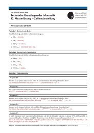
5 3 Ü 5 㪠) binary XOR operations <strong>for</strong> one polynomial reduction. Reduction of<br />
pentanomials can be per<strong>for</strong>med similar leading to some additional XOR operations. The particular terms<br />
(1...5) of the final equation are structured according to Fig. 2.3 in order to per<strong>for</strong>m the reduction. With<br />
respect to the implementation a single( -bit register is sufficient to store the resulting bit string.<br />
åYºæ<br />
å3 æ<br />
å8 æ<br />
å$Aæ<br />
åèç æ<br />
¢ £h¤ ¥<br />
¢ £¤ ¥<br />
¢ £¤ ¥<br />
¢ £h¤ ¥<br />
¢ £¤ ¥<br />
) = Y ã<br />
) ã Y<br />
) ã Y<br />
) = Y<br />
±ÈÇÉ® Ò ±K5 ±<br />
±ÈÇÉ® Ò ±ª 5 㪠±<br />
±–ÇÉ® Ò 3 = 㪠±5 㪠±<br />
±ÈÇÉ® Ò 3 P 㪠±5 ±<br />
±ÈÇÉ® Ò ª ±K5 ±<br />
n−1 0<br />
(1)<br />
2n−1<br />
2n−b−1 n 2n−1 2n−b<br />
(2) (4)<br />
2n−1<br />
(5)<br />
2n−b<br />
(3)<br />
Result Register (n bit)<br />
Figure 2.3: Structure of the polynomial reduction<br />
n
2.3. SEQUENTIAL MULTIPLICATION SCHEMES 13<br />
Due to the complexity of a reduction step, in the following this work diverts the arithmetic operations in<br />
into two successive parts. The arithmetical operation:hÁ5. corresponding to that in- and<br />
with a degreeÕ<br />
( and the subsequent reduction step.<br />
2.3 Sequential Multiplication Schemes<br />
In order to achieve a reasonable level of security <strong>for</strong> an EC cryptosystem, the extension degree ( of the<br />
underlying finite field has to be in the hundreds. Due to chip area limitations an application of<br />
combinational multipliers of full bit width ( is usually not feasible. Instead, a sequential multiplication<br />
scheme, which is <strong>based</strong> on a reasonable sized purely combinational multiplier unit, has to be utilized. In<br />
Sec. 3.4.4 the architecture of such a combinationalhÁ5. multiplier is presented, which is scalable and<br />
highly efficient in terms of required logic resources.<br />
In the remainder of this section it is assumed that a reasonable sized combinational multiplier, which<br />
computes the unreduced product of two degree +êé ( polynomials, is part of the design. Some wellknown<br />
methods <strong>for</strong> sequential multiplication are introduced first. Then, in Sec. 2.3.3, the Multi-Segment<br />
Karatsuba multiplication scheme is detailed and compared to classical approaches.<br />
2.3.1 Schoolbook Multiplication<br />
Given two polynomialsv<br />
@ |ëE -hÁ5ÃÂ of degree( and a combinational multiplier of size+<br />
6ëì(b†¦kí ,<br />
the product} 6 v |<br />
can be computed as follows: Firstv<br />
and|<br />
are split each into two segments of equal<br />
size.<br />
Then the product can be computed as<br />
6 v YC5 î 3 ¾ v ® v<br />
6 | YC5 î 3 ¾ | ® |<br />
6 v | }<br />
v Yg5 î 3 ¾ v ®ZaP| Yg5 î 3 ¾ | ® 6<br />
v YÚ | YC5 ¾Æv YÚ | ®Ú¾ v ®j | Y[º5 î 3 ¾ v ®j | ®k\ (2.10)<br />
6<br />
Please note that in the context of hardware implementations the5<br />
±<br />
factors correspond to position offsets,<br />
which can simply be implemented by appropriate wiring.<br />
Generally, the polynomials can be split into an arbitrary number of segments<br />
E”© ª<br />
. It is selected such<br />
that the resulting segments are small enough to be multiplied on the combinational multiplier (+ ³ (b†¦ ).<br />
The number of necessary multiplications is given by<br />
3<br />
. Since the additions can be computed combinationally<br />
in the same cycle, the cycle count <strong>for</strong> a complete multiplication is also given by<br />
3<br />
.<br />
A variation of the schoolbook method splits each of the two polynomialsv<br />
and|<br />
into different numbers<br />
of segments (=ïÚ@A=ð .) Of course, in this case an appropriate asymmetric combinational multiplier is necessary<br />
2 . The number of required multiplications is given here by.ïˆBPð . In the extreme case of4ï 6 ( and<br />
=ð 6 c this scheme is called bit serial multiplication.<br />
2 This topic is extensively treated in [16].
2.3. SEQUENTIAL MULTIPLICATION SCHEMES 14<br />
x^ 8<br />
x^ 7<br />
x^ 6<br />
x^ 5<br />
x^ 4<br />
x^ 3<br />
x^ 2<br />
x^ 1<br />
x^<br />
a)<br />
0<br />
x^<br />
b)<br />
8<br />
x^<br />
7<br />
x^<br />
6<br />
x^<br />
5<br />
x^<br />
4<br />
x^<br />
3<br />
x^<br />
2<br />
x^<br />
1<br />
x^<br />
0<br />
3<br />
23<br />
A 3*B3<br />
A 3*B2<br />
A 2*B3<br />
A 3*B1<br />
A 2*B2<br />
A 1*B3<br />
A 3*B0<br />
A 2*B1<br />
A 1*B2<br />
A 0*B3<br />
A 2*B0<br />
A 1*B1<br />
A 0*B2<br />
A 1*B0<br />
A 0*B1<br />
A 0*B0<br />
13<br />
0123<br />
2<br />
02<br />
1<br />
01<br />
0<br />
A*B<br />
A*B<br />
c)<br />
x^ 8<br />
x^ 7<br />
x^ 6<br />
x^ 5<br />
x^ 4<br />
x^ 3<br />
x^ 2<br />
x^ 1<br />
x^ 0<br />
x^ 8<br />
x^ 7<br />
x^ 6<br />
x^ 5<br />
x^ 4<br />
x^ 3<br />
x^ 2<br />
x^ 1<br />
x^<br />
d)<br />
3<br />
0<br />
23<br />
3<br />
123<br />
23<br />
12<br />
23<br />
2<br />
3<br />
0123<br />
123<br />
012<br />
1<br />
2<br />
012<br />
01<br />
12<br />
01<br />
1<br />
0<br />
0<br />
123<br />
0123<br />
2<br />
12<br />
012<br />
1<br />
01<br />
0<br />
A*B<br />
A*B<br />
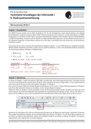
Figure 2.4: Sequential Multiplication Schemes: a) Schoolbook method; b) unrolled Karatsuba <strong>for</strong> 2 recursion<br />
steps; c)! #"%$ be<strong>for</strong>e reordering of the subterms; d)& œ"H$ after reordering of the subterms
6 v | }<br />
v Yg5 ¦î 3 ¾ v ®SaP| Yg5 î 3 ¾ | ®S 6<br />
v Y | Yg5 ¾ v Y | ®[5 î 3 ¾ v ® | Yg5 ¦î 3 ¾ v ® | ®<br />
6<br />
6 v Y | Y<br />
ú<br />
ü v Y | Y<br />
ü v ® | ®<br />
Y 0ó6 v Y | Y l<br />
3 0ó6 v Ya¾ v ®Sb=| Ya¾ | ®S l<br />
v Y | ®Ú¾ v ® | YD¾ v Y | Yb¾ v ® | ® 6<br />
l<br />
8<br />
8<br />
8<br />
2.3. SEQUENTIAL MULTIPLICATION SCHEMES 15<br />
Fig. 2.4a illustrates the schoolbook multiplication <strong>for</strong> 6°ñ<br />
. The gray boxes represent the results of<br />
the degree+ respective polynomial multiplications, which are denoted next to the boxes. The horizontal<br />
position of a box indicates its ò 5 0ó6 59ô offset . The ordering of the partial products by<br />
¯<br />
decreasing<br />
allows <strong>for</strong> the accumulation of the final result in a shift register and the application of an interleaved<br />
reduction scheme as detailed in Sec. 3.4.6.<br />
5 ±<br />
with ò<br />
2.3.2 Polynomial Karatsuba Multiplication<br />
In 1963 A. Karatsuba and Y. Ofman developed an algorithm of complexity õ7K(Úöø÷Cù 8 that computes the<br />
product of two( -bit integers [17].<br />
Like the Schoolbook Multiplication, this algorithm divides the operands into two equal parts. Adopting<br />
the arithmetical operations tohÁ5. leads to<br />
¢ £h¤ ¥<br />
¢ £¤ ¥<br />
¢ £h¤ ¥<br />
¢ £h¤ ¥<br />
¢ £h¤ ¥<br />
úû 5 ¾ÆÁ–v Ya¾ v ®Sh| Ya¾ | ®S<br />
úBý ÂÈ5 î 3 ¾ v ® | ®<br />
úû<br />
úBý<br />
6 l Y 5 ¾²Ál 3 ü l Y ü l<br />
8 ÂÈ5 ¦î 3 ¾ l<br />
8<br />
(2.11)<br />
6 l Y 5 ¾²Ál Y ¾ l 3 ¾ l<br />
8<br />
given by<br />
8 ÂÈ5 ¦î 3 ¾ l<br />
withl<br />
YZ@ l 3 andl<br />
v ® | ®k\ 0ó6<br />
Thus, the final product can be computed by 3 multiplications and 2 additions degree(b†¦ of polynomials<br />
and 4 additions degree( of polynomials as illustrated in Fig. 2.5. Again, since the addition can be computed<br />
combinationally in the same cycle as a partial multiplication, the complete multiplication takes 3 cycles<br />
only. By splitting the into<br />
6 ±<br />
factors segments any¯ EN©<br />
(<strong>for</strong> ), the product can be withþ=öø÷Cù ¦<br />
computed<br />
multiplications by a recursive application of this scheme.<br />
Due to the need to store intermediate results and to maintain a stack, recursive algorithms are not appropriate<br />
<strong>for</strong> hardware implementations. The recursion has thus to be unrolled. Fig. 2.4b shows the resulting<br />
degree+<br />
multiplication scheme <strong>for</strong> an unrolled recursion of the Karatsuba with<br />
6Šñ<br />
multiplication . Each pattern<br />
in Fig. 2.4b, which is additionally surrounded by a gray box, can be composed from one partial multiplication.<br />
The labels at the right side of the boxes determine the indices of the segments, whose sums have been<br />
multiplied. E.g., the label "13" denotes the termv<br />
Ya¾ v<br />
8 .<br />
6 v Y | ®Ú¾ v ® | YD¾ l Ya¾ l<br />
8 b=| Yb¾ |
6 v |!6 v 3 5 3 î 8 ¾ v Yg5 î 8 ¾ v ®S#P| 3 5 3 ¦î 8 ¾ | YC5 ¦î 8 ¾ | ®Z<br />
}<br />
v 3 | 3 5 $ î 8 ¾Æv 3 | YD¾ v Y | 3 º5 ¾²v 3 | ®:¾ v Y | Yb¾ v ® | 3 º5 3 î 8<br />
6<br />
Y | ®:¾ v ® | Y[º5 î 8 ¾Æv ® | ®Z ¾7v<br />
6 v 3 | 3<br />
ú<br />
ü v Y | Y<br />
2.3. SEQUENTIAL MULTIPLICATION SCHEMES 16<br />
m/2<br />
m/2−1 1 m/2−1 m/2<br />
T 1<br />
T 1<br />
T 2<br />
T 3<br />
m/2<br />
A=A 1x + A 0<br />
m/2<br />
B=B 1x + B0<br />
T 1=A 1B1<br />
T =(A +A )(B +B )<br />
2 1 0 1 0<br />
T T =A B<br />
3 3 0 0<br />
. A B<br />
2m−1<br />
Figure 2.5: Polynomial Karatsuba multiplication scheme<br />
2.3.3 Multi-Segment Karatsuba Multiplication<br />
The basic Karatsuba multiplication <strong>for</strong> polynomials in-hÁ5. is <strong>based</strong> on the idea of divide and conquer,<br />
since the operands are divided into two segments each.<br />
One may attempt to generalize this idea by subdividing the operands into more than two segments. [18]<br />
reports on such an implementation with a fixed number of three segments denoted as Karatsuba-variant<br />
multiplication.<br />
The proof <strong>for</strong> that multiplication scheme follows directly out of the classical Karatsuba algorithm by<br />
dividing the operands into three parts:<br />
¢ £¤ ¥<br />
¢ £h¤ ¥<br />
¢ £h¤ ¥<br />
¢ £h¤ ¥<br />
ü v 3 | 3<br />
úû<br />
úû 5 $ î 8 ¾ÆÁ–v 3 ¾ v Y[h| 3 ¾ | YX<br />
úBý ÂÈ5 <br />
ü l 3 ü l<br />
(2.12)<br />
3 ¾ v Ya¾ v ®Sh| 3 ¾ | Ya¾ | ®Z ¢ £¤ ¥ ¾7Á–v<br />
8 ü l ç ü l<br />
8 ÂÈ5 3 î 8<br />
úBÿ<br />
Ya¾ v ®Zh| Y#¾ | ®Z ¢ £h¤ ¥ ¾7Á–v<br />
¢ £h¤ ¥<br />
¢ £h¤ ¥<br />
¢ £h¤ ¥<br />
Comparing Eqn. 2.11 and Eqn. 2.12 one might assume that a generalized Karatsuba scheme is possible by<br />
following the same scheme again. This assumption has been verified <strong>for</strong>ñ<br />
to ¤ segments manually. This<br />
had lead to a generalized scheme that will be called Multi-Segment Karatsuba (MSK). Disregarding some<br />
slight arithmetic variations, the Karatsuba-variant multiplication is a special case of the MSK approach. The<br />
MSK multiplication scheme, which is proposed in this work, is more general because an arbitrary number<br />
of segments is supported.<br />
Two polynomials of degree ( over -hÁ5ÃÂ are multiplied by a -segment Karatsuba multiplication<br />
ú ¡<br />
ü v Y | Y<br />
ü v ® | ®<br />
úBý<br />
ÂÈ5 î 8:¾ v ® | ®<br />
ú£¢ ú£¢
Ô<br />
Ô<br />
Ô<br />
2.3. SEQUENTIAL MULTIPLICATION SCHEMES 17<br />
#" ¦ ) 3 in the following way: It is assumed that ( ͉Ï4Ð 6°I<br />
; if not, the polynomials are padded<br />
with the necessary number of zero coefficients. A polynomial<br />
v E hÁ5. is divided into segments<br />
(!<br />
Y ±ÈÇÉ® v ±ä`ò 5 ±<br />
, with ò 5 0ó6 5 ¦î ¦<br />
. With Eqn. 2.13} 6 v |]6 ! #" ¦ v @ | holds <strong>for</strong> any<br />
¦<br />
such thatv 6¦¥<br />
degree( polynomialsv<br />
@ |ËE -hÁ5. :<br />
5 ± Yª ¦ <br />
(2.13)<br />
whereas<br />
& œ" ¦ v @ | <br />
6¨§<br />
¦<br />
5 ± Y<br />
¾<br />
§<br />
¦ Y<br />
±ÈÇbY ±©®v @ | #ò<br />
±ÈÇbY<br />
¦ ±©± v @ | aò<br />
© v @ | 6 § ô Y Ô<br />
±ÈÇbY<br />
±© v @ | <br />
<br />
ô<br />
§ ô Y Ô<br />
±–ÇbY<br />
±© ª ô ± v @ | <br />
<br />
¾? ô © v @ | 9@ (2.14)<br />
¾<br />
| ±<br />
<br />
\ ±ÈÇ ±ÈÇ<br />
The annex of this paper presents an example application of the <strong>for</strong>& #" 8<br />
above equations .<br />
According to Eqn. 2.13 product} 6 v | 6 ! #" ¦ v @ | the entire is composed of the partial sums<br />
v @ | . Each partial sum consists of partial products ô © v @ | according to Eqn. 2.14. The total<br />
©<br />
,. number of (b†¦ required -bit multiplications in order to per<strong>for</strong>m ( one -bit multiplication using<br />
ô<br />
#" ¦<br />
the<br />
scheme results from !<br />
Y© v @ | 6 Y© v @ | and ô © v @ | 6 §<br />
ª ô Y<br />
ô Y Ô ª<br />
v ±<br />
<br />
<br />
§<br />
6 Ì ¯ ¦ 6 M)²cS#B<br />
\ (2.15)<br />
2.3. SEQUENTIAL MULTIPLICATION SCHEMES 18<br />
to the rectangles determine the indices of the segments, whose sums have been multiplied. E.g., the label<br />
”123” represents termv<br />
YP¾ v 3 ¾ v<br />
8 =A| Y4¾ | 3 ¾ |<br />
8 the , which denoted<br />
8 ©øYSv @ | is in Eqn. 2.14. The<br />
horizontal position of a rectangle represents exponent¯<br />
the of the associated ò 5 ±<br />
factor . E.g., the rectangle<br />
in the lower left edge labeled ”3” together with its position denotes the v<br />
8 ¾ |<br />
8 Pò 5 term . The<br />
} 6 v |<br />
result<br />
is computed by summing up (XORing) all the terms according to their horizontal position. This<br />
final is product segments wide, as one would expect. The partial products can be reordered as shown in<br />
Fig. 2.4d. This order was achieved from a consideration of three optimization criteria.<br />
First, most partial products are added two times to compute the final result. They can be grouped together<br />
and placed in one of three patterns, which are indicated in Fig. 2.4d. This is true <strong>for</strong> all instances of the<br />
MSK algorithm (again this has been evaluated semi-manually by a C program <strong>for</strong> Õ c II<br />
any ). In the<br />
architecture detailed in Sec. 3, these patterns are computed by some additional combinational logic, which<br />
is connected to the output of the combinational multiplier.<br />
Second, the resulting patterns are ordered descending¯<br />
by of their ò factor<br />
±<br />
. In this way, the product can<br />
be accumulated easily in a shift register.<br />
5<br />
As the third optimization criterion the remaining degree of freedom is taken advantage of in the following<br />
way: The patterns are once more reordered, such that when iterating over them from top to bottom, one of<br />
two conditions holds: Either the current pattern is constructed from a single segment (e.g.v<br />
®j | ® product ,<br />
but v ®j¾ v YXœ| ®j¾ | Y not ) or the set of indices of the pattern segments differs only at one index from<br />
its predecessor (as in the productsv<br />
® | ® andv<br />
®¾ v Y[#=| ®:¾ | YX partial ). Since this criterion can not<br />
always be met <strong>for</strong> all segments some accumulation steps take one additional cycle. However it can be shown<br />
that it is always possible to reorder the segments in a way that either the sum of up to two single segments or<br />
at most two additional segments need to be accumulated. A fact that already has been proven and has been<br />
evaluated <strong>for</strong> interesting all , too.<br />
By applying the third optimization criterion to the pattern sequence, the partial product computations<br />
can be per<strong>for</strong>med as follows: By + placing -bit accumulator registers at the inputs of the combinational<br />
multiplier, from which each can add up one segment to the current value or load one new segment in a<br />
single clock cycle, terms<br />
ô © v @ | the can be computed iteratively in a pipelined fashion (see Fig. 3.2).<br />
This results in a two stage pipelined design <strong>for</strong> the complete datapath and yields a total cZ of clock cycles<br />
to per<strong>for</strong>m one multiplication the! #"'$ using .<br />
The MSK scheme has a slight per<strong>for</strong>mance disadvantage in terms of + required -bit multiplications in<br />
comparison to the classical Karatsuba algorithm (11% ! #"¨$ <strong>for</strong> and 33% ! #" <strong>for</strong> ), but there are<br />
considerable benefits:<br />
First, the number segments of that the polynomials are divided into is not limited to be a power of two,<br />
but can be any natural number when the MSK scheme is applied. With respect to a HW implementation<br />
this provides more flexibility concerning the selection of system parameters. Like stated be<strong>for</strong>e, segment<br />
counts in range<br />
E JBþ4@\–\–@PR the provide the best results; a fact that can be uniquely exploited by the MSK<br />
approach.<br />
Second, each time an additional level of recursion unrolling is applied to the classical Karatsuba algorithm,<br />
two new patterns occur in the multiplication scheme, whose size is growing exponentially by a factor of 2<br />
(compare Fig. 2.5 to Fig. 2.4b.) In contrast, <strong>for</strong> any of value the number of different patterns will<br />
exceedþ<br />
never<br />
in case of the MSK scheme. This fact allows the efficient multiplication of polynomials of different<br />
degrees on the same datapath: If, e.g., the underlying supports datapath any& œ" segments, scheme<br />
x Õ <br />
<strong>for</strong><br />
can be per<strong>for</strong>med just by modification of the controller which is running the MSK algorithm.
Chapter 3<br />
<strong>Hardware</strong> Architecture<br />
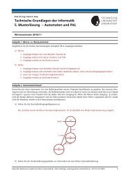
The architecture of the EC coprocessor (depicted in Fig. 3.1) mainly consists of four modules denoted as<br />
part (a) to (d). It has been implemented on several <strong>FPGA</strong> plat<strong>for</strong>ms (see Chap. 4 <strong>for</strong> implementation results)<br />
which allowed fast and easy practical evaluation of the design.<br />
Since the implementation of the modules (a) to (c) is basically straight <strong>for</strong>ward and not expensive in<br />
terms of logic resources Sec. 3.1 to Sec. 3.3 give a brief overview on these components. In Sec. 3.4 the<br />
more complex and resource intensive finite field arithmetic is described in detail. Finally the software parts<br />
(VHDL generator and evaluation software) are illustrated in Sec. 3.5 and Sec. 3.6.<br />
a)<br />
b)<br />
Address<br />
16 * n bit<br />
Register File<br />
DataFromPci<br />
DataToPci<br />
PCI<br />
Interface<br />
c)<br />
d)<br />
Interrupt<br />
EC Arithmetic<br />
FF Arithmetic<br />
Figure 3.1: Generic Datapath of the EC coprocessor<br />
3.1 PCI Interface<br />
The interface component denoted as part (a) in Fig. 3.1 provides the external 32-bit wide PCI interface and an<br />
internal( -bit wide interface to the Register File. Data <strong>for</strong>mats are converted across the interface by the use<br />
of appropriate shift registers. Most of this module could be reused from the previous ONB implementation.
3.2. REGISTER FILE 20<br />
3.2 Register File<br />
Part (b) of Fig. 3.1 covers the Register File. It provides c registers of( -bit width. These registers are<br />
implemented by using <strong>FPGA</strong> internal Lookup Tables (LUT) and provide a dual ported interface allowing<br />
concurrent read and write access to the data. Currently ¤ registers are used as internal temporary registers<br />
<strong>for</strong> the EC algorithms and can there<strong>for</strong>e not be accessed by the user. The remaining ¤ register are left <strong>for</strong><br />
field parameters, input operands and results. By modifying the EC level algorithms the requirements <strong>for</strong><br />
internal temporary registers might change.<br />
3.3 EC Arithmetic<br />
The EC Arithmetic, highlighted as part (c) in Fig. 3.1, implements the algorithm and the underlying<br />
EC operations EC-Add and EC-Double. It also implements the FF-Inversion that is intrinsically not an<br />
EC level operation. But since it is realized by the control flow oriented algorithm and composed of basic<br />
arithmetic operations in just like the EC level operations, FF-Inversion has been implemented here<br />
(see Alg. 4).<br />
Beside of the controller the module contains a single shift register of( -bit size. This register is needed to<br />
scan bit-wise as required by Eqn. 3.<br />
The controller is implemented by several Finite State Machines (FSM) in a hierarchical order. Each FSM<br />
controls one arithmetical operation, i.e., the algorithm, the EC-Add and the EC-Double operation.<br />
The hierarchical ordering of FSMs is considered to be the best tradeoff between speed and flexibility.<br />
Leaving the controller logic inside the software would provide more flexibility <strong>for</strong> changing EC level algorithms<br />
at the cost that pipelining delays and parallel operation of different modules becomes much more<br />
complicated (or might even be impossible). Furthermore the overhead and the delay <strong>for</strong> communication over<br />
the PCI interface makes this solution impracticable. The other way would be a single controller to prevent<br />
possible delays emerging from communication between the different FSMs. The great disadvantage of this<br />
approach is, that due to the unmanageable side-effects inside such an FSM, modifications of one algorithm<br />
(e.g. the EC algorithm) would lead to a rewrite of the whole controller and not just the EC controller.<br />
3.4 Finite Field Arithmetic<br />
The finite field arithmetic that is denoted as part (d) in Fig. 3.1 is the most expensive part of the EC coprocessor.<br />
Due to the complexity it is split into separate modules that provide the functionality of the operations<br />
described in Sec. 2.2. A general overview of the datapath is given in Fig. 3.2. The particular parts depicted<br />
in this picture are described subsequently and the corresponding gate counts are summarized in Tab. 3.2.<br />
3.4.1 Addition<br />
According to Eqn. 2.4 the addition inhÁ5ÃÂ is a just an( -bit wide XOR with no need <strong>for</strong> a subsequent<br />
reduction step. A complete addition can be per<strong>for</strong>med in one cycle. So part (a) of Fig. 3.2 takes( XORgates<br />
of logic resources <strong>for</strong> it’s implementation. Please note, that the input registers are part of the Register<br />
File and the result register is used by all finite field operations together, because of which it’s FlipFlops are<br />
counted only once in part (f).
3.4. FINITE FIELD ARITHMETIC 21<br />
Input Register<br />
Input Register<br />
c)<br />
’0’<br />
’0’<br />
n n<br />
n n<br />
(k+1):1 MUX<br />
m<br />
’0’<br />
2:1 MUX<br />
(k+1):1 MUX<br />
m<br />
’0’<br />
2:1 MUX<br />
a) b)<br />
m−bit register<br />
m<br />
m−bit register<br />
m<br />
d)<br />
Add<br />
Square &<br />
Reduce<br />
m−bit CKM<br />
2m−1<br />
e) f)<br />
Shift Left<br />
n<br />
n<br />
3:1 MUX<br />
4m−2<br />
Reduce<br />
2:1 MUX<br />
n<br />
n<br />
3:1 MUX<br />
n−bit register<br />
Figure 3.2: Generic Datapath of the Finite Field Arithmetic<br />
3.4.2 Square<br />
Following from Eqn. 2.6 squaring in hÁ5. is done by inserting a constant "0" at every second bit<br />
position. In hardware this can be done at nearly no cost by appropriate wiring of the signals. The subsequent<br />
reduction can be done according to Sec. 2.2.8. However the need <strong>for</strong> k( )w> binary XOR gates that are<br />
mentioned there is an upper bound <strong>for</strong> the resource requirement of the square module. Since half of the<br />
bits in the unreduced intermediate result are constant "0" some XOR gates are dispensable. Because of that,<br />
the exact number of XOR gates is remarkable smaller than k(”) > and depends on the particular prime<br />
polynomial. In the following k( )w> binary XOR gates will be used as a suitable approximation <strong>for</strong> the<br />
resource usage of the square module. As in the case of addition the square module that is depicted as part<br />
(b) Fig. 3.2 takes only a single clock cycle.
3.4. FINITE FIELD ARITHMETIC 22<br />
3.4.3 Input Stage<br />
The input stage provides two accumulation registers, i.e., one <strong>for</strong> each operand of the combinational multiplier.<br />
Besides parallel load functionality these registers must be capable of adding one new segment to its<br />
current value, as stated in Sec. 2.3.3. According to part (c) of Fig. 3.2 the following logic gatecounts are<br />
required to build up the input stage <strong>for</strong> a& #" ¦ <strong>based</strong> on a+ -bit combinational multiplier:<br />
6 k+ "!ƒe 3$#YBK+F@A. 6 k+&% v<br />
<br />
€ 3 K+ˆ 6dñ + e('U 3 K+ˆ 6 k+<br />
npn*K+ˆ<br />
remark:"!ƒe 3$#Y Please components with constant zero inputs have been tov<br />
<br />
€ 3 optimized gates.<br />
3.4.4 Combinational Multiplier (CKM)<br />
As stated be<strong>for</strong>e in Sec. 2.2.1 and shown in Fig. 3.3a the product of two one bit polynomials is computed by<br />
a single AND operation.<br />
a a b<br />
3 2 3<br />
a a b 1 0 1<br />
a 0 b 0<br />
c 2<br />
c 0<br />
c 1<br />
c 0<br />
c c c c c<br />
6 5 4 3<br />
c c<br />
2 1 0<br />
b 0<br />
a 1<br />
a 0<br />
b 1<br />
b 0<br />
CKM2<br />
CKM2<br />
CKM1<br />
CKM1<br />
CKM2<br />
CKM1<br />
b<br />
2<br />
a) 1−bit CKM<br />
b) 2−bit CKM<br />
c) 4−bit CKM<br />
Figure 3.3: Recursive construction process <strong>for</strong> polynomial Karatsuba multipliers<br />
Using Karatsuba’s divide and conquer multiplication algorithm, a multiplication of two( -bit polynomials<br />
can be computed with three(b†¦ -bit multiplications and some additions (which are XOR’s in our case) to<br />
determine interim results and accumulate the final result. This leads immediately to a recursive construction<br />
process, which builds combinational Karatsuba multipliers (CKM) of width(<br />
6 ô <strong>for</strong> arbitrary+<br />
E
3.4. FINITE FIELD ARITHMETIC 23<br />
Thus, we can calculate the number of gates of an+ -bit CKM with the following recurrences:<br />
e)'U 3 K+ˆ<br />
6+*<br />
I + 6 c<br />
3 K+ˆ†¦«+ ´ c e('U 8 K+ˆ<br />
6+*<br />
I + 6 c<br />
c:)?þe('U 8 K+ˆ†¦ + ´ c<br />
+¢)Wþe)'pU<br />
<br />
€ 3 K+ˆ<br />
6+* c + 6 c<br />
þ v<br />
<br />
€ 3 K+ˆ†¦«+ ´ c e)'U $ K+ˆ<br />
6+*<br />
I + 6 c<br />
+ _ ¨)?þe)'pU-$PK+ˆ†¦ + ´ c<br />
v<br />
With the master method [19] it can easily be shown that all of these recurrences belong to the complexity<br />
õ7K+¨öø÷Cù 8 class . The ofv<br />
<br />
€ 3 number gates exactly+¨öø÷Cù 8 is . By substituting a 3-input XOR by<br />
e('U 3<br />
two<br />
and a 4-input XOR threee)'pU 3 by gates, an upper bound on requirede('U 3 the count is be given<br />
k+Nöø÷Cù 8 by . Some gate counts <strong>for</strong> multipliers of various operand bit widths are summarized in Tab. 3.1 and<br />
illustrated in Fig. 3.4.<br />
v<br />
<br />
€ 3<br />
e('U 3<br />
e('U 8 e('U-$<br />
Table 3.1:<br />
Bit Width 1 2 4 8 16 32 64<br />
1 3 9 27 81 243 729<br />
0 2 10 38 130 422 1330<br />
0 0 2 12 50 180 602<br />
0 1 4 13 40 121 364<br />
,! 1 6 25 90 301 966 3025<br />
3500<br />
3000<br />
2500<br />
2000<br />
gate count<br />
1500<br />
1000<br />
500<br />
0<br />
4<br />
8<br />
16<br />
bit width<br />
32<br />
64<br />
AND2<br />
gate type<br />
XOR4<br />
XOR3<br />
SUM<br />
XOR2<br />
Figure 3.4: Combinational Karatsuba Multiplier gate count<br />
3.4.5 MSK Pattern Generation<br />
As detailed in Sec. 2.3.3 there are three different MSK patterns which are build <strong>based</strong> on the output of the<br />
CKM. A simplified illustration of the corresponding architecture is shown in part (e) of Fig. 3.2. In practice,<br />
the pattern creation is implemented by various multiplexers. Moreover, in case of the& œ" 8<br />
scheme, the<br />
patterns will exceed the bit width( of the affiliated"!ƒe<br />
8 #Y and there<strong>for</strong>e have to be reduced be<strong>for</strong>e they
Ì<br />
Ì<br />
Ì<br />
Ì<br />
Ì<br />
3.4. FINITE FIELD ARITHMETIC 24<br />
can be added to the intermediate result. This leads to approximately k+ additional e)'U 3 gates <strong>for</strong> a<br />
! #" 8<br />
design. In general, an optimized multiplexer structure leads to the following resource requirement:<br />
3 K+ˆ 6 + -!-e 3$#YZK+ˆ 6 k+ v<br />
<br />
€ 3 K+ˆ 6 k+<br />
e('U<br />
3.4.6 Interleaved Polynomial Reduction<br />
A first naive design approach may per<strong>for</strong>m the polynomial reduction after the calculation of the complete<br />
multiplication. According to Eqn. 2.9, such a architecture would requirek( ) >#e('U 3 gates. Furthermore,<br />
this would lead to datapaths and multiplexers of sizek( _ c . To keep the datapaths on a maximum size of<br />
( a method of interleaved reduction has been developed.<br />
When utilizing the MSK multiplication scheme <strong>based</strong> on + a -bit CKM the maximum degree of each<br />
intermediate is( )Q+ result with+/. ( , . only( )Q+ There<strong>for</strong>e, bit values have to be reduced in each<br />
iteration. Regarding this fact Eqn. 2.9 reads as<br />
} 6 = Yª ô Ì<br />
Ò ±K5 ± Ü = Y<br />
±ÈÇÉ® Ò ±z5 ± ) P Yª ô<br />
±ÈÇÉ®<br />
±–Ç Ò ±CK5 ±. ),5 㪠±. Í7ÏÐ <br />
@ (3.1)<br />
which results in a total of onlyk+]e('U 3 gates <strong>for</strong> the polynomial reduction. The particular terms (1...3)<br />
of Eqn. 3.1 are structured according to Fig. 3.5 in order to calculate the reduction. Within the MSK scheme,<br />
this kind of interleaved reduction of degree ( )²+ polynomials is per<strong>for</strong>med each time the intermediate<br />
result is shifted left by+ bit.<br />
n−1 0<br />
(1)<br />
n−1+m<br />
(3)<br />
n−1+m<br />
(2)<br />
n<br />
n<br />
6 = Y<br />
±ÈÇÉ®#Ò ±5 ±<br />
±–ÇÉ®Ò ±ª 5 㪠±<br />
±ÈÇÉ®Ò ±ª 5 ±<br />
) ô Y<br />
) ô Y<br />
åYºæ<br />
å3 æ<br />
å8 æ<br />
¢ £h¤ ¥<br />
¢ £h¤ ¥<br />
¢ £h¤ ¥<br />
Result Register (n bit)<br />
Figure 3.5: Structure of the polynomial reduction of(*),+ bit<br />
The gatecount calculation <strong>for</strong> part (f) of Fig. 3.2 is as follows: As already mentioned, the reduction of<br />
degree()*+ polynomials takesk+!e)'pU 3 gates. Additionally,+<br />
¯(:K(œ@ ñ + _ Fe)'U 3 gates are required<br />
to per<strong>for</strong>m the accumulation of the actual MSK pattern to the current result value. Finallyþk(D"!ƒe 3$#Y are<br />
needed to choose if the result of an addition, square or multiply operation is stored in the result register.<br />
Summing up, this results in the following resource requirement:<br />
npn%K(b 6 ( e('U 3 K+ˆ 6 + ¯(:K(œ@ ñ + _ `)?k+ -!-e 3$#YBK(b 6dñ (
D<br />
SUM E K]GiD Qlk DHGIeGk KNGR KTSVUXW Y [mGnK_^`DbacDedZLfKhgnEfj R KNGnK_SoUpW Y [ E KNMPOqGJEFK]GnLfD<br />
3.5. VHDL-CODE GENERATOR 25<br />
Table 3.2: Datapath gatecount<br />
010 24365,7 8:9@?,2A7B C<br />
Datapath<br />
Part (a)<br />
Part (b)<br />
EFDHGJI<br />
Part E K L£K E KNMPO<br />
(c)<br />
Part Q)R KTSVUXWZYX[ KTSVUXWZY\[<br />
(d)<br />
Part K E K EFK<br />
(e)<br />
Part D E K]GK_^`DbacDedZLfKhgiEfj LfD<br />
(f)<br />
3.5 VHDL-Code Generator<br />
In this section the VHDL-Code Generator is presented. Though VHDL offers several possibilities to generalize<br />
code statements this opportunities are not sufficient to implement a design as scalable as required<br />
in this application. E.g., it would not be possible to generalize the reduction logic due to the variable<br />
prime polynomials. To provide the wanted scalability a generator <strong>based</strong> approach proposed in [10] has been<br />
adopted where the VHDL code is generated by a C program. The generator consists of one top-level file<br />
calculating some internal variables out of the user input parameters, opening the files into which the VHDL<br />
code is written and calling the appropriate subroutines. Each subroutine is implemented in a separate file<br />
and generates the VHDL description (entity and architecture) <strong>for</strong> one particular hardware module.<br />
The generator takes several parameters that are implemented as commandline parameters. Currently these<br />
parameters are:<br />
Key Size [Bits]:<br />
r<br />
The Key Size specifies the overall bit width of the coprocessor. A given constraint is that this number<br />
must be smaller than the CKM size multiplied by the number of segments.<br />
Combinational Karatsuba Multiplier (CKM) size [Bits]:<br />
r<br />
The CKM size specifies the width of the combinational part of the multiplier. Since the size of the<br />
CKM is exponentially dependent on it’s bit width, this value is essential determining the resource<br />
consumption of the complete ECC coprocessor.<br />
Bit Position of the middle bit in the prime trinomial [Int]:<br />
r<br />
The bit position of the middle bit in the prime trinomial is needed <strong>for</strong> reduction component. The<br />
position of the highest bit is already specified by the key size and and the lowest bit is fixed be5<br />
®<br />
to .<br />
The current generator is only capable of trinomials. Supporting pentanomials would be possible by<br />
slight modifications of the generator.<br />
Number of Segments [Int]:<br />
r<br />
The type of MSK is specified by the number of segments. Currently the generator is limited from<br />
three to seven segments which are regarded as the most interesting ones. Additional support of new<br />
MSK sizes can be applied by adding a new subroutine to the ’generate_ff_controller’ routine in the<br />
generator program. Outside the controller the number of segments does not have any influences to the<br />
design.<br />
Card Type [1|2]:<br />
r<br />
The card type specifies which hardware dependent top level module should be instantiated. ’1’ is
3.6. EVALUATION SOFTWARE 26<br />
used <strong>for</strong> the microEnable plat<strong>for</strong>m board, ’2’ is used <strong>for</strong> ADM-XRC-II plat<strong>for</strong>m. For details on these<br />
plat<strong>for</strong>ms see Chap. 4. This option has no effect on the functional part of the design.<br />
3.6 Evaluation Software<br />
To evaluate the presented hardware design it is necessary to provide a software that can communicate with<br />
the <strong>FPGA</strong> on the one hand, and that can compare hardware results with software results that are considered<br />
as correct. To provide this functionality the existing evaluation software (ECCLib) has been enhanced. The<br />
previous software provided EC level arithmetic, finite field level arithmetic <strong>for</strong> ONB representation and an<br />
interface to the microEnable PCI card.<br />
As part of this work a second finite field level arithmetic <strong>for</strong> polynomial representation has been implemented<br />
<strong>based</strong> on [20]. Besides some simple modifications the EC level algorithms could be reused and a<br />
new runtime switch has been added to the software to determine which representation should be used.<br />
At second, an interface to the new Alpha Data ADM-XRC-II <strong>FPGA</strong> plat<strong>for</strong>m has been added, that is also<br />
selected by a runtime option in the software. This second hardware plat<strong>for</strong>m allows the evaluation of a<br />
greater range of parameter sets and there<strong>for</strong>e illustrates the flexibility of the presented design.<br />
The hardware has successfully been tested by per<strong>for</strong>ming operations with randomly generated parameters.<br />
Currently the implementation uses memory mapped I/O <strong>for</strong> communication between software and<br />
<strong>FPGA</strong> board which seems to allow a sufficient data transfer rate. The termination of a computation is<br />
signaled to the software via Interrupts.
In t e r f a c e sXtuovxw<br />
Chapter 4<br />
Implementation Results<br />
Various instances of the presented architecture have been implemented and evaluated within several <strong>FPGA</strong><br />
devices. These widely used devices are typical representatives of different complexity classes ranging from<br />
a low-cost device that might be interesting <strong>for</strong> client-side applications up to a high-end chip that is of special<br />
interest <strong>for</strong> high-per<strong>for</strong>mance server applications.<br />
In the following, the different plat<strong>for</strong>ms are briefly introduced and in Sec. 4.4 the implementation results<br />
are summarized.<br />
4.1 Xilinx XC4085XLA<br />
One of the outlined implementations is <strong>based</strong> on the microEnable PCI card (illustrated in Fig. 4.1) from<br />
Silicon Software GmbH [21]. This card is equipped with a <strong>FPGA</strong> from Xilinx, Inc. [8], in which the<br />
coprocessors functionality is implemented. The card is available with <strong>FPGA</strong>s of different complexities. In<br />
our case the XC4085XLA, a medium-sized <strong>FPGA</strong> with a complexity of max. 180K system gates is used.<br />
Furthermore the card comes with a programmable clock generator, static RAM, and external interfaces. The<br />
integration into a target system is accomplished via the PCI interface. The XC4085XLA <strong>FPGA</strong> allows the<br />
RAM<br />
RAM<br />
<strong>FPGA</strong><br />
y{zf|~}<br />
z €‚|o}<br />
RAM<br />
RAM<br />
PCI<br />
ĉ‰ Š ‹Œ<br />
RAM<br />
„Z…$„‡<br />
microEnable<br />
ycģ|~}<br />
„Z…$„\†<br />
Figure 4.1: microEnable PCI card
4.2. XILINX XCV405E 28<br />
implementation of a CKM with a maximum width of 64 bit within the datapath. The exact number varies<br />
on other generator parameters such as the number of segments.<br />
4.2 Xilinx XCV405E<br />
The XCV405E <strong>FPGA</strong> device from Xilinx, Inc. is a high-end <strong>FPGA</strong> providing 400K system gates. This<br />
device allows the implementation of a CKM with up to 85 bits. Due to the newer technology and powerful<br />
routing resources higher frequencies can be achieved compared to the XC4085XLA device. Similar to the<br />
XC4085XLA the XCV405E is applied on a PCI interface card. This ADM-XRC-II plat<strong>for</strong>m from Alpha<br />
Data, Inc. [22] provides a <br />
ñ<br />
-bit wide PCI interface and 6M Bytes SRAM. It supports up to two different<br />
Xilinx VirtexE or Virtex2 <strong>FPGA</strong> devices on one PCI interface card.<br />
4.3 Atmel AT94K40<br />
The AT94K40 from Atmel, Inc. [9] is a System-on-Chip device. As illustrated in Fig. 4.2 it provides an 8 bit<br />
AVR Ž processor core, <strong>FPGA</strong> resources, some peripherals and up to 36K Byte of SRAM on a single chip.<br />
With only 40K system gates the <strong>FPGA</strong> resources are limited and allow the implementation of a maximum<br />
width of 25 bit <strong>for</strong> the CKM. Compared to the Xilinx <strong>based</strong> implementations which use the PCI bus <strong>for</strong> the<br />
communication with the software running on the host system, the AT94K40 provides a low latency interface<br />
between <strong>FPGA</strong> hardware part and Ž processor core that is capable of 8 bit transfers in each clock cycle.<br />
Figure 4.2: Atmel AT94K40<br />
Due to these features it is reasonable to run the EC level algorithms in software on the Ž processor core.<br />
By this, the replacement of the EC algorithms proposed in Chap. 2 with the better per<strong>for</strong>ming 2P algorithm<br />
documented in [23] could realized easily.
‘ 6 c "!”“<br />
l 6<br />
<br />
ÞxµBÙ 3 4áj)²c I<br />
v €H€½6 )’<br />
ÞxµBÙ 3 4á)@ :VU 6 ÞxµBÙ 3 4áj)?þ<br />
þ<br />
4.4. COMPARISON 29<br />
The 2P algorithm, which is furthermore considered to be more resistant against Side-Channel-Attacks<br />
consists of three different EC level algorithms and a modified algorithm.<br />
Looking at the EC level algorithms, Mdouble per<strong>for</strong>ms a variation of the classical EC-Double operation.<br />
The EC-Add operation is exchanged by the Madd operation. The Mxy operations is used to transfer the result<br />
from the internal projective coordinate representation back to the affine representation. All these algorithms<br />
are given in the Annex of this work.<br />
The entire 2P algorithm per<strong>for</strong>ms the following number of arithmetic operations in .<br />
4.4 Comparison<br />
Tab. 4.1 gives a summary of some implementations that are considered to have the most interesting parameter<br />
sets <strong>for</strong> the proposed hardware plat<strong>for</strong>ms. Since the VHDL generator currently only supports the<br />
Double-And-Add algorithm <strong>for</strong> a genuine hardware implementation, the values <strong>for</strong> the 2P algorithm on Xilinx<br />
plat<strong>for</strong>ms are estimated. Please note, that due to the application two pipeline stages within the datapath<br />
the number of clock cycles <strong>for</strong> a complete FF-Mult operation is increased by two compared to Eqn. 2.15.<br />
Because of resource problems the AT94K40 implementation has only one pipeline stage applied, which<br />
results in one additional clock cycle. In the case of the Double-And-Add algorithm the hamming-weight<br />
of is approximated with (b†¦ . A comparison of the AT94K40 implementation to other state-of-the-art<br />
implementations has been recently published in [24].<br />
Table 4.1: Implementation results<br />
Target plat<strong>for</strong>m Atmel Xilinx<br />
AT94K40 XC4085XLA XC4085XLA XCV405E<br />
degree(<br />
size+<br />
segments<br />
Ž<br />
Ž Ž Ž<br />
finite field 113 191 239 409<br />
CKM bit 23 64 60 82<br />
MSK 5 3 4 5<br />
clock cycles per FF-Mult 17 8 12 18<br />
Device utilization 96 % 76 % 81 % 97 %<br />
Operating frequency 12 MHz 33 MHz 31 MHz 60 MHz<br />
Double-And-Add n/a 742.9 s 1.4 ms 1.7 ms<br />
2P algorithm 1.4 ms 395.9 s 759.9 s 926.8 s<br />
The Xilinx <strong>based</strong> designs have been synthesized with <strong>FPGA</strong> Compiler II v3.7 from Synopsys, Inc. The<br />
<strong>FPGA</strong> Mapping has been done with ISE v4.2 from Xilinx, Inc. The implementations <strong>for</strong> the Atmel device<br />
have been synthesized using Leonardo v2000.1b from Mentor, Inc. and have been mapped to the chip<br />
utilizing Figaro IDS v7.5 from Atmel, Inc.
Chapter 5<br />
Conclusions and Outlook<br />
5.1 Summary<br />
With the MSK, this work presented a new algorithm <strong>for</strong> multiplication in that is considered to<br />
be more efficient in terms of time and logic resource requirements than any other approach known to the<br />
author. A corresponding hardware architecture has been developed and integrated into an elliptic curve<br />
coprocessor. The entire EC coprocessor has been implemented on different <strong>FPGA</strong> devices. The functionality<br />
of these implementations has been evaluated by comparing the hardware results with that of a corresponding<br />
software solution.<br />
Due to the application of a VHDL generator approach, the presented design is widely scalable by modification<br />
of the number of segments and/or the size of the combinational multiplier. By utilizing that generator<br />
it is possible to create new design variants with different parameters at minimal ef<strong>for</strong>t.<br />
Because of the fact that a finite field multiplication takes a constant amount of clock cycles and processes<br />
various bits in parallel the design is resistant against currently known Side-Channel-Attacks <strong>based</strong> on the<br />
measurement of computing time or power consumption.<br />
5.2 Further Work<br />
There were several topics arising during the treatment of this work which could not be finally addressed.<br />
In the present design, the input stage in Fig. 3.2c allows the accumulation of one single segment to the current<br />
value of the CKM input register only. This leads to CKM idle cycles if the number of segments becomes<br />
greater than 4. Regarding the fact that it is always possible to reorder the segments in a way that adding or<br />
loading of at most two segments will be sufficient to do an MSK-<strong>based</strong> multiplication without idle cycles of<br />
the CKM, a modified input stage would be reasonable. The implementation of such a modified input stage<br />
would take only a little more hardware resources but will gain a further per<strong>for</strong>mance enhancement.<br />
The effects of applying the MSK scheme inside the combinational multiplier should be investigated. Especially<br />
on hardware plat<strong>for</strong>ms where <strong>for</strong> some reason a combinational multiplier of a given bitwidth can<br />
be utilized the modification of the presented CKM component might be interesting.<br />
As detailed in Chap. 4 the 2P algorithm that is currently only used in the AT94K40 <strong>based</strong> implementation<br />
would give a significant per<strong>for</strong>mance enhancement compared to the currently used Double-And-Add<br />
algorithm when implemented entirely in hardware on Xilinx <strong>based</strong> plat<strong>for</strong>ms.<br />
Currently the generator provides a set of hard-coded FSMs <strong>for</strong> the most interesting number of segments.
5.2. FURTHER WORK 31<br />
It should be possible to apply the <strong>for</strong>mula of the MSK scheme to the generator, in order to derive FSM<br />
modules <strong>for</strong> arbitrary segment numbers at generator runtime.<br />
Though the MSK algorithm has been evaluated manually <strong>for</strong> the interesting range of segments the general<br />
mathematical proof is still interesting. Actually, there are people working on the proof and it is probable<br />
that the MSK scheme will soon be proven.<br />
Acknowledgment<br />
The author would like to thank Markus Ernst and Michael Jung <strong>for</strong> their great help and support.
Bibliography<br />
[1] National Institute of Standards and Technology, “Data Encryption Standard,” Federal<br />
In<strong>for</strong>mation Processing Standard (FIPS) Publication 46-2 (supercedes FIPS-46-1),<br />
http://www.itl.nist.gov/div897/pubs/fip46-2.htm, December 1993.<br />
[2] National Institute of Standards and Technology, “Specification <strong>for</strong> the Advanced Encryption<br />
Standard (AES),” Federal In<strong>for</strong>mation Processing Standard (FIPS) Publication 197,<br />
http://csrc.nist.gov/publications/fips/fips197/fips-197.pdf, November 26, 2001.<br />
[3] Internet Engineering Task Force, “The TLS Protocol,” RFC 2246,<br />
http://www.ietf.org/rfc/rfc2246.txt, January 1999.<br />
[4] R. L. Rivest, A. Shamir and L. M. Adleman, “A Method <strong>for</strong> Obtaining Digital Signatures and Public-<br />
Key Cryptosystems,” Communications of the ACM, Feb 1978.<br />
[5] V. Miller, “Use of elliptic curves in cryptography,” Advances in Cryptology, Proc. CRYPTO’85,<br />
LNCS 218, H. C. Williams, Ed., Springer-Verlag, pp. 417–426, 1986.<br />
[6] N. Koblitz, “<strong>Elliptic</strong> <strong>Curve</strong> Cryptosystems,” Mathematics of Computation, vol. 48, pp. 203–209,<br />
1987.<br />
[7] A. Lenstra and E. Verheul, “Selecting Cryptographic Key Sizes,” Proc. Workshop on Practice and<br />
Theory in Public Key <strong>Cryptography</strong>, Springer-Verlag, ISBN 3540669671, pp. 446–465, 2000.<br />
[8] Xilinx, “Programmable Logic Data Book,” 2001.<br />
[9] Atmel, Inc. “Configurable Logic Data Book,” 2001.<br />
[10] M. Ernst, S. Klupsch, O. Hauck and S. A. Huss, “Rapid Prototyping <strong>for</strong> <strong>Hardware</strong> Accelerated<br />
<strong>Elliptic</strong> <strong>Curve</strong> Public-Key Cryptosystems,” Proc. 12th IEEE Workshop on Rapid System Prototyping<br />
(RSP01), Monterey, CA, June 2001.<br />
[11] A. J. Menezes, “<strong>Elliptic</strong> <strong>Curve</strong> Public Key Cryptosystems,” Kluwer Akademic Publishers, 1993.<br />
[12] J. H. Silverman, “The Arithmetic of <strong>Elliptic</strong> <strong>Curve</strong>s,” Graduate Texts in Mathematics, Springer-<br />
Verlag, 1986.<br />
[13] IEEE 1363, “Standard Specifications For Public Key <strong>Cryptography</strong>,”<br />
http://grouper.ieee.org/groups/1363/, 2000.<br />
[14] ANSI X9.62, “Public key cryptography <strong>for</strong> the financial services industry: The <strong>Elliptic</strong> <strong>Curve</strong> Digital<br />
Signature Algorithm (ECDSA),” (available from the ANSI X9 catalog), 1999.
BIBLIOGRAPHY 33<br />
[15] J. Lopez and R. Dahab, “Improved algorithms <strong>for</strong> elliptic curve arithmetic in<br />
„ n% ,” Selected<br />
Areas in <strong>Cryptography</strong> (SAC’98), LNCS 1556, Springer-Verlag, pp. 201–212, 1998.<br />
[16] S. Okada, N. Torii, K. Itoh and M. Takenaka, “Implementation of <strong>Elliptic</strong> <strong>Curve</strong> Cryptographic<br />
Coprocessor over on an <strong>FPGA</strong> ,” Workshop on Cryptographic <strong>Hardware</strong> and Embedded<br />
Systems (CHES 2000), LNCS 1965, C.K. Koc and C. Paar Eds., Springer-Verlag, pp.25–40, 2000.<br />
[17] A. Karatsuba and Y. Ofman, “Multiplication of multidigit numbers on automata,” Sov. Phys.-Dokl<br />
(Engl. transl.), vol. 7, no. 7, pp. 595-596, 1963.<br />
[18] D. V. Bailey and C. Paar, “Efficient Arithmetic in Finie Field Extensions with Application in <strong>Elliptic</strong><br />
<strong>Curve</strong> <strong>Cryptography</strong>,” Journal of Cryptology, vol. 14, no. 3, pp. 153–176, 2001.<br />
[19] J. L. Bentley, D. Haken and J. B. Saxe, “A general method <strong>for</strong> solving divide-and-conquer recurrences,”<br />
SIGACT News, vol. 12(3), pp. 36–44, 1980.<br />
[20] M. Rosing, “Implementing <strong>Elliptic</strong> <strong>Curve</strong> Cryptogarphy,” Manning Publications Co., ISBN 1-<br />
884777-69-4, Greenwich, 1999.<br />
[21] Silicon Software, “microEnable Users Guide,” 1999.<br />
[22] Alpha Data Parallel Systems Ltd., “ADC-PMC-64 User Manual”, Ver. 1.1, 2002.<br />
[23] J. Lopez and R. Dahab, “Fast multiplication on elliptic curves over<br />
„ n*ô without precomputation,”<br />
Workshop on Cryptographic <strong>Hardware</strong> and Embedded Systems (CHES 99), LNCS 1717,<br />
C.K. Koc and C. Paar Eds., Springer-Verlag, pp. 316–327, 1999.<br />
[24] M. Ernst, M. Jung, F. Madlener, S. Huss and R. Bluemel, “A Reconfigurable System on Chip Implementation<br />
<strong>for</strong> <strong>Elliptic</strong> <strong>Curve</strong> <strong>Cryptography</strong> over- ,” Workshop on Cryptographic <strong>Hardware</strong><br />
and Embedded Systems (CHES 2002), Springer-Verlag, 2002.
Ô Ô<br />
bY©®v @ | ò<br />
6<br />
6 Y©® v @ | ò<br />
ò<br />
ò<br />
ò<br />
6 WY©®v @ | ò<br />
ò<br />
ò<br />
ò<br />
ò<br />
ò<br />
ò<br />
ò<br />
ò<br />
ò<br />
ò<br />
ò<br />
ò<br />
ò<br />
ò<br />
ANNEX 34<br />
Annex A: 3-Segment Karatsuba Multiplication<br />
For any polynomialsv<br />
and|<br />
over- the product} 6 v |½6 & #" 8 v @ | using the 3-segment<br />
Karatsuba multiplication according to Eqn. 2.13 is given by:<br />
! #" 8 v @ | <br />
6¨§ 8<br />
5 ± Y<br />
¾<br />
§<br />
3<br />
5 ±ª 3 <br />
±ÈÇbY ±©®¦v @ | aäò<br />
±ÈÇbY 8 ±©±Cv @ | aÉò<br />
5 ® ¾<br />
©®v @ | ò 5 Y ¾<br />
3<br />
©® v @ | ò 5 3 ¾<br />
8<br />
©øY v @ | ò 5 8 ¾<br />
3<br />
Y©3 v @ | <br />
5 $<br />
5 ® ¾<br />
u Y©® v @ | `¾W Y©øY v @ | D¾? 3 ©® <br />
5 Y ¾<br />
u Y©® v @ | `¾W 3 ©® v @ | D¾W Y©3 v @ | `¾O 3 ©øY v @ | `¾? 8 ©® v @ | C<br />
5 3 ¾<br />
u bY©øYSv @ | `¾W bY©3 v @ | D¾? 3 ©øYBv @ | C<br />
5 8 ¾<br />
WY©®v @ | ò 5 ® ¾<br />
6<br />
WY©3 v @ | <br />
5 $<br />
WY©®v @ | `¾O bY©®v @ | `¾W aY©øYZv @ | `¾? 3 ©®v @ | `¾?WY©3 v @ | C¾<br />
WY©®v @ | `¾W?Y©øYSv @ | D¾? 3 ©®v @ | C<br />
5 Y ¾<br />
bY©øYSv @ | `¾W bY©3 v @ | D¾? 3 ©øYBv @ | `¾< 8 ©®v @ | C<br />
5 3 ¾<br />
WY©øYBv @ | `¾W?Y©3 v @ | D¾? 3 ©øYBv @ | C<br />
5 8 ¾<br />
WY©®v @ | ò 5 ® ¾<br />
6<br />
WY©3 v @ | <br />
5 $<br />
WY©®v @ | `¾W?Y©®v @ | D¾??Y©øYBv @ | `¾? 3 ©®v @ | `¾?WY©3 v @ | C¾<br />
WY©®v @ | `¾W?Y©øYSv @ | D¾? 3 ©®v @ | C<br />
5 Y ¾<br />
WY©øYBv @ | `¾
Input: An integer<br />
³ I<br />
and a Point<br />
6 K5D@ 1 EN/<br />
Output: the5 -coordinatee%†i <strong>for</strong> the point¦<br />
Ym l<br />
Ò<br />
Ym‚i@% l Y l<br />
returnê @Xi<br />
Y<br />
Ò<br />
ANNEX 35<br />
Annex B: 2P Algorithm<br />
Algorithm 5 2P Algorithm (Montgomery Scalar Multiplication )<br />
6 <br />
if<br />
6²I<br />
or5<br />
6²I<br />
the output(0,0) and stop.<br />
Output:V<br />
Y \–\–\ Y ® 3 .<br />
Set*mÓ<br />
Y m°5b@Xi Y mÓc¦@Ce 3 m°5 $ )?>B@Xi 3 mo5 3<br />
.<br />
<strong>for</strong>¯<br />
fromx _ downtoI<br />
do<br />
Sete<br />
6 c then<br />
w; {P{ Ke'YS@XiYZ@Ce 3 @Xi 3 , { µ r>[xtPKe 3 @Xi 3 .<br />
if±<br />
w; {P{ Ke 3 @Xi 3 @Ce'YZ@XijY[ , { µ r>[xtPKe'YS@XijY[<br />
else<br />
returnuV<br />
6 w5 1 Ke'YZ@XijYZ@Ce 3 @Xi 3 C<br />
.<br />
Algorithm 6 Mdouble<br />
Input: the field ; the field elements; and<br />
Ò<br />
6 ><br />
3•—–<br />
û<br />
3 6 > defining a curve/<br />
over: ;<br />
the5 -coordinate <strong>for</strong> a Point .<br />
eÖm°e 3<br />
i²m‚i 3<br />
l Ym l 3 i²m‚i@%:e<br />
eÖm°e 3<br />
eÖm°e]) l Y
3 m°e'Ỹ %jijY l<br />
Y<br />
Ym°5 l<br />
l<br />
$ƒm l 8 Y l<br />
l<br />
l $) l 3 $ƒm<br />
8<br />
l<br />
8<br />
ANNEX 36<br />
Algorithm 7 Madd<br />
Input: the field¦ ; the field elements; and> defining a curve/<br />
over-P. ;<br />
-coordinate of the Point P; the5 -coordinatese Y[†iY ande 3 †i 3 <strong>for</strong> the pointsY and 3 on/<br />
.<br />
Output: the5 -coordinateë Y[†iY <strong>for</strong> the pointYa)< 3<br />
the5<br />
Ym°5 l<br />
e'Ym e'Ỹ %i 3<br />
ijYm‚iỸ %e 3<br />
ijYm‚iYa)